Information injection-pump assembly
BOSCH
9 460 614 564
9460614564
ZEXEL
104745-9410
1047459410
NISSAN
167002H210
167002h210
Rating:
Cross reference number
BOSCH
9 460 614 564
9460614564
ZEXEL
104745-9410
1047459410
NISSAN
167002H210
167002h210
Zexel num
Bosch num
Firm num
Name
Calibration Data:
Adjustment conditions
Test oil
1404 Test oil ISO4113orSAEJ967d
1404 Test oil ISO4113orSAEJ967d
Test oil temperature
degC
45
45
50
Nozzle
105780-0060
Bosch type code
NP-DN0SD1510
Nozzle holder
105780-2150
Opening pressure
MPa
13
13
13.3
Opening pressure
kgf/cm2
133
133
136
Injection pipe
157805-7320
Injection pipe
Inside diameter - outside diameter - length (mm) mm 2-6-450
Inside diameter - outside diameter - length (mm) mm 2-6-450
Joint assembly
157641-4720
Tube assembly
157641-4020
Transfer pump pressure
kPa
20
20
20
Transfer pump pressure
kgf/cm2
0.2
0.2
0.2
Direction of rotation (viewed from drive side)
Right R
Right R
Injection timing adjustment
Pump speed
r/min
1100
1100
1100
Average injection quantity
mm3/st.
44.2
43.7
44.7
Difference in delivery
mm3/st.
4
Basic
*
Oil temperature
degC
50
48
52
Injection timing adjustment_02
Pump speed
r/min
500
500
500
Average injection quantity
mm3/st.
38
35
41
Oil temperature
degC
48
46
50
Injection timing adjustment_03
Pump speed
r/min
850
850
850
Average injection quantity
mm3/st.
41.2
38.7
43.7
Oil temperature
degC
50
48
52
Injection timing adjustment_04
Pump speed
r/min
1100
1100
1100
Average injection quantity
mm3/st.
44.2
43.2
45.2
Difference in delivery
mm3/st.
4.5
Basic
*
Oil temperature
degC
50
48
52
Injection timing adjustment_05
Pump speed
r/min
2150
2150
2150
Average injection quantity
mm3/st.
46
43.5
48.5
Oil temperature
degC
52
50
54
Injection quantity adjustment
Pump speed
r/min
2550
2550
2550
Average injection quantity
mm3/st.
18.5
16.5
20.5
Basic
*
Oil temperature
degC
55
52
58
Injection quantity adjustment_02
Pump speed
r/min
2800
2800
2800
Average injection quantity
mm3/st.
5
Oil temperature
degC
55
52
58
Injection quantity adjustment_03
Pump speed
r/min
2400
2400
2400
Average injection quantity
mm3/st.
37.4
32.9
41.9
Oil temperature
degC
52
50
54
Injection quantity adjustment_04
Pump speed
r/min
2550
2550
2550
Average injection quantity
mm3/st.
18.5
15.5
21.5
Basic
*
Oil temperature
degC
55
52
58
Governor adjustment
Pump speed
r/min
350
350
350
Average injection quantity
mm3/st.
8.9
6.9
10.9
Difference in delivery
mm3/st.
2
Basic
*
Oil temperature
degC
48
46
50
Governor adjustment_02
Pump speed
r/min
350
350
350
Average injection quantity
mm3/st.
8.9
6.4
11.4
Difference in delivery
mm3/st.
2.5
Basic
*
Oil temperature
degC
48
46
50
Timer adjustment
Pump speed
r/min
100
100
100
Average injection quantity
mm3/st.
48.9
43.9
53.9
Basic
*
Oil temperature
degC
48
46
50
Remarks
Full
Full
Timer adjustment_02
Pump speed
r/min
100
100
100
Average injection quantity
mm3/st.
48.9
43.9
53.9
Oil temperature
degC
48
46
50
Remarks
Full
Full
Speed control lever angle
Pump speed
r/min
350
350
350
Average injection quantity
mm3/st.
0
0
0
Oil temperature
degC
48
46
50
Remarks
Magnet OFF at idling position
Magnet OFF at idling position
0000000901
Pump speed
r/min
1100
1100
1100
Overflow quantity
cm3/min
390
260
520
Oil temperature
degC
50
48
52
Stop lever angle
Pump speed
r/min
1100
1100
1100
Pressure
kPa
490
461
519
Pressure
kgf/cm2
5
4.7
5.3
Basic
*
Oil temperature
degC
50
48
52
Stop lever angle_02
Pump speed
r/min
1100
1100
1100
Pressure
kPa
490
451
529
Pressure
kgf/cm2
5
4.6
5.4
Basic
*
Oil temperature
degC
50
48
52
Stop lever angle_03
Pump speed
r/min
1700
1700
1700
Pressure
kPa
637
598
676
Pressure
kgf/cm2
6.5
6.1
6.9
Oil temperature
degC
50
48
52
0000001101
Pump speed
r/min
1100
1100
1100
Timer stroke
mm
4.2
4
4.4
Basic
*
Oil temperature
degC
50
48
52
_02
Pump speed
r/min
700
700
700
Timer stroke
mm
1.9
1.5
2.3
Oil temperature
degC
50
48
52
_03
Pump speed
r/min
1100
1100
1100
Timer stroke
mm
4.2
3.9
4.5
Basic
*
Oil temperature
degC
50
48
52
_04
Pump speed
r/min
1700
1700
1700
Timer stroke
mm
7.3
6.8
7.8
Oil temperature
degC
50
48
52
_05
Pump speed
r/min
2200
2200
2200
Timer stroke
mm
9
8.5
9.4
Oil temperature
degC
52
50
54
0000001201
Max. applied voltage
V
8
8
8
Test voltage
V
13
12
14
0000001401
Pump speed
r/min
1100
1100
1100
Average injection quantity
mm3/st.
32
31.5
32.5
Timer stroke TA
mm
2.9
2.7
3.1
Timer stroke variation dT
mm
1.3
1.3
1.3
Basic
*
Oil temperature
degC
50
48
52
_02
Pump speed
r/min
1100
1100
1100
Average injection quantity
mm3/st.
32
31
33
Timer stroke TA
mm
2.9
2.6
3.2
Basic
*
Oil temperature
degC
50
48
52
_03
Pump speed
r/min
1100
1100
1100
Average injection quantity
mm3/st.
22
19.5
24.5
Timer stroke TA
mm
1.6
1.2
2
Oil temperature
degC
50
48
52
Timing setting
K dimension
mm
3.3
3.2
3.4
KF dimension
mm
6.36
6.26
6.46
MS dimension
mm
0.9
0.8
1
Control lever angle alpha
deg.
25
23
27
Control lever angle beta
deg.
36
31
41
Test data Ex:
0000001801 STOP LEVER ADJUSTMENT
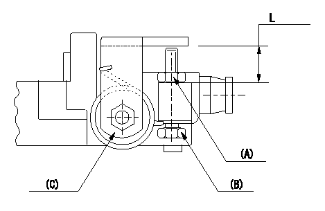
Adjustment of the stop lever
Adjust adjusting bolt (B) so that the starting injection quantity is within the standard.
Fix using nut.
(A) Adjusting nut
(C) Starting injection quantity adjusting lever
----------
----------
L=15.0~18.5mm
----------
----------
L=15.0~18.5mm
Information:
1. Remove the seat retaining ring (1) and pin (2). 2. Remove the seat (3), bolt (4), washers (5) and spring (6).3. Remove the sleeve and bearing assembly from the cylinder and weight assemblies. 4. Remove the retaining ring (7) from sleeve (8).5. Remove bearing (9) and races (10) from sleeve (8). 6. Remove the valve (11) from piston (12).7. Remove the cylinder-to-weight assembly retaining ring (13).8. Remove the weight assembly (14).9. Remove piston (12) and sleeve (15) from the cylinder (16).10. Remove the O-ring seal from the sleeve (15). 11. Remove the speed limiter plug (17), spring (18), and plunger (19) from the governor housing.12. Remove the high idle screw (21) and low idle screw (20). 13. Remove the lever assembly-to-shaft assembly retaining bolt (23) and lock.14. Remove the shaft assembly (22) and lever assembly (24) from governor housing.15. Remove the seal from governor housing. 16. Remove two retaining bolts (25) and lock. Remove the lever (26) and shaft (27) from idle screw housing.17. Remove two seals and bearing from idle screw housing.Assemble Governor
1. Using tool (A) install the inner seal in idle screw housing with spring side of seal facing the driver. Install bearing and outer seal with lip of the seal toward the inside of the housing. Lubricate lip of seal with clean SAE 30 engine oil.2. Position the shaft and lever in the idle screw housing. Install the retaining bolts and lock. 3. Using tool (A), install the seal in the governor housing with spring side of seal toward inside of governor housing. Lubricate lip of seal with clean SAE 30 engine oil.4. Position the lever assembly and shaft in the governor housing. Install the retaining bolt and lock.5. Install the high and low idle screws in the governor housing.6. Install the speed limiter plug, spring, and plunger in the governor housing. 7. Install the O-ring seal (3) on sleeve (4).8. Install piston (2) and sleeve (4) in the cylinder (1). 9. Position the weight assembly (6) on cylinder (7), and install retaining ring (5). 10. Install the valve (9) in piston (10).11. Install the bearing and races in sleeve. Install retaining ring. Install the sleeve and bearing assembly (8) on valve (9). 12. Position the seat (12), bolt (11), washers and spring on the valve (9). Install the retaining pin (14) and retaining ring (13).concluding step: a) connect governor to fuel injection pump housing
1. Using tool (A) install the inner seal in idle screw housing with spring side of seal facing the driver. Install bearing and outer seal with lip of the seal toward the inside of the housing. Lubricate lip of seal with clean SAE 30 engine oil.2. Position the shaft and lever in the idle screw housing. Install the retaining bolts and lock. 3. Using tool (A), install the seal in the governor housing with spring side of seal toward inside of governor housing. Lubricate lip of seal with clean SAE 30 engine oil.4. Position the lever assembly and shaft in the governor housing. Install the retaining bolt and lock.5. Install the high and low idle screws in the governor housing.6. Install the speed limiter plug, spring, and plunger in the governor housing. 7. Install the O-ring seal (3) on sleeve (4).8. Install piston (2) and sleeve (4) in the cylinder (1). 9. Position the weight assembly (6) on cylinder (7), and install retaining ring (5). 10. Install the valve (9) in piston (10).11. Install the bearing and races in sleeve. Install retaining ring. Install the sleeve and bearing assembly (8) on valve (9). 12. Position the seat (12), bolt (11), washers and spring on the valve (9). Install the retaining pin (14) and retaining ring (13).concluding step: a) connect governor to fuel injection pump housing