Information injection-pump assembly
ZEXEL
104745-9350
1047459350
Rating:
Cross reference number
ZEXEL
104745-9350
1047459350
Zexel num
Bosch num
Firm num
Name
104745-9350
INJECTION-PUMP ASSEMBLY
Calibration Data:
Adjustment conditions
Test oil
1404 Test oil ISO4113orSAEJ967d
1404 Test oil ISO4113orSAEJ967d
Test oil temperature
degC
45
45
50
Nozzle
105780-0060
Bosch type code
NP-DN0SD1510
Nozzle holder
105780-2150
Opening pressure
MPa
13
13
13.3
Opening pressure
kgf/cm2
133
133
136
Injection pipe
157805-7320
Injection pipe
Inside diameter - outside diameter - length (mm) mm 2-6-450
Inside diameter - outside diameter - length (mm) mm 2-6-450
Joint assembly
157641-4720
Tube assembly
157641-4020
Transfer pump pressure
kPa
20
20
20
Transfer pump pressure
kgf/cm2
0.2
0.2
0.2
Direction of rotation (viewed from drive side)
Right R
Right R
Injection timing adjustment
Pump speed
r/min
1100
1100
1100
Average injection quantity
mm3/st.
49.9
49.4
50.4
Difference in delivery
mm3/st.
4
Basic
*
Oil temperature
degC
50
48
52
Injection timing adjustment_02
Pump speed
r/min
500
500
500
Average injection quantity
mm3/st.
41.3
38.8
43.8
Oil temperature
degC
48
46
50
Injection timing adjustment_03
Pump speed
r/min
1100
1100
1100
Average injection quantity
mm3/st.
49.9
48.9
50.9
Difference in delivery
mm3/st.
4.5
Basic
*
Oil temperature
degC
50
48
52
Injection timing adjustment_04
Pump speed
r/min
2150
2150
2150
Average injection quantity
mm3/st.
46.3
43.8
48.8
Oil temperature
degC
52
50
54
Injection quantity adjustment
Pump speed
r/min
2550
2550
2550
Average injection quantity
mm3/st.
10.9
8.9
12.9
Difference in delivery
mm3/st.
3
Basic
*
Oil temperature
degC
55
52
58
Injection quantity adjustment_02
Pump speed
r/min
2700
2700
2700
Average injection quantity
mm3/st.
5
Oil temperature
degC
55
52
58
Injection quantity adjustment_03
Pump speed
r/min
2350
2350
2350
Average injection quantity
mm3/st.
39.7
39.7
39.7
Oil temperature
degC
52
50
54
Injection quantity adjustment_04
Pump speed
r/min
2550
2550
2550
Average injection quantity
mm3/st.
10.9
8.4
13.4
Basic
*
Oil temperature
degC
55
52
58
Governor adjustment
Pump speed
r/min
350
350
350
Average injection quantity
mm3/st.
7.7
5.7
9.7
Difference in delivery
mm3/st.
2
Basic
*
Oil temperature
degC
48
46
50
Governor adjustment_02
Pump speed
r/min
350
350
350
Average injection quantity
mm3/st.
7.7
5.2
10.2
Difference in delivery
mm3/st.
2.5
Basic
*
Oil temperature
degC
48
46
50
Timer adjustment
Pump speed
r/min
100
100
100
Average injection quantity
mm3/st.
60
45
80
Basic
*
Oil temperature
degC
48
46
50
Remarks
Full
Full
Timer adjustment_02
Pump speed
r/min
100
100
100
Average injection quantity
mm3/st.
60
45
80
Oil temperature
degC
48
46
50
Remarks
Full
Full
Speed control lever angle
Pump speed
r/min
350
350
350
Average injection quantity
mm3/st.
0
0
0
Oil temperature
degC
48
46
50
Remarks
Magnet OFF at idling position
Magnet OFF at idling position
0000000901
Pump speed
r/min
1100
1100
1100
Overflow quantity with S/T ON
cm3/min
390
260
520
Oil temperature
degC
50
48
52
Remarks
With S/T O-ring; S/T ON.
With S/T O-ring; S/T ON.
_02
Pump speed
r/min
1100
1100
1100
Overflow quantity with S/T ON
cm3/min
600
470
730
Oil temperature
degC
50
48
52
Remarks
Without S/T O-ring; S/T ON.
Without S/T O-ring; S/T ON.
Stop lever angle
Pump speed
r/min
1100
1100
1100
Pressure with S/T ON
kPa
520
481
559
Pressure with S/T ON
kgf/cm2
5.3
4.9
5.7
Pressure with S/T OFF
kPa
431
402
460
Pressure with S/T OFF
kgf/cm2
4.4
4.1
4.7
Basic
*
Oil temperature
degC
50
48
52
Remarks
OFF
OFF
Stop lever angle_02
Pump speed
r/min
1100
1100
1100
Pressure with S/T OFF
kPa
431
392
470
Pressure with S/T OFF
kgf/cm2
4.4
4
4.8
Basic
*
Oil temperature
degC
50
48
52
Stop lever angle_03
Pump speed
r/min
1700
1700
1700
Pressure with S/T OFF
kPa
559
520
598
Pressure with S/T OFF
kgf/cm2
5.7
5.3
6.1
Oil temperature
degC
50
48
52
0000001101
Pump speed
r/min
1100
1100
1100
Timer stroke with S/T ON
mm
3.4
3
3.8
Timer stroke with S/T OFF
mm
1.9
1.7
2.1
Basic
*
Oil temperature
degC
50
48
52
Remarks
OFF
OFF
_02
Pump speed
r/min
850
850
850
Timer stroke with S/T OFF
mm
0.5
0
1
Oil temperature
degC
50
48
52
_03
Pump speed
r/min
1100
1100
1100
Timer stroke with S/T ON
mm
3.4
2.9
3.9
Timer stroke with S/T OFF
mm
1.9
1.6
2.2
Basic
*
Oil temperature
degC
50
48
52
_04
Pump speed
r/min
1700
1700
1700
Timer stroke with S/T OFF
mm
4.4
3.9
4.9
Oil temperature
degC
50
48
52
_05
Pump speed
r/min
2300
2300
2300
Timer stroke with S/T OFF
mm
6.1
5.6
6.5
Oil temperature
degC
52
50
54
0000001201
Max. applied voltage
V
8
8
8
Test voltage
V
13
12
14
0000001401
Pump speed
r/min
1100
1100
1100
Average injection quantity
mm3/st.
31
30.5
31.5
Timer stroke TA
mm
1.2
1
1.4
Timer stroke variation dT
mm
0.7
0.7
0.7
Basic
*
Oil temperature
degC
50
48
52
_02
Pump speed
r/min
1100
1100
1100
Average injection quantity
mm3/st.
31
30
32
Timer stroke TA
mm
1.2
0.9
1.5
Basic
*
Oil temperature
degC
50
48
52
_03
Pump speed
r/min
1100
1100
1100
Average injection quantity
mm3/st.
22
19.5
24.5
Timer stroke TA
mm
0.6
0.1
1.1
Oil temperature
degC
50
48
52
Timing setting
K dimension
mm
3.3
3.2
3.4
KF dimension
mm
5.8
5.7
5.9
MS dimension
mm
0.9
0.8
1
Pre-stroke
mm
0.1
0.08
0.12
Control lever angle alpha
deg.
25
23
27
Control lever angle beta
deg.
36
31
41
Test data Ex:
0000001801 POTENTIOMETER ADJUSTMENT
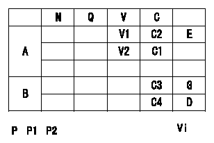
A:Potentiometer standards
B:ON, OFF switch standard
G:ON-->OFF
D:OFF-->ON
E:Adjusting point
F:Checking point
P:Boost pressure
Vi:Applied voltage
C1:Full-speed
C2:Idle
Q:Injection quantity
N:Pump speed
V:Output voltage
C:Control lever angle
----------
----------
V1=1.6+-0.03V V2=7.6+-1.1V C3=(4.9+-2.5)deg C4=(19.4+-4)deg Vi=10V P1=-kPa P2=-mmHg
----------
----------
V1=1.6+-0.03V V2=7.6+-1.1V C3=(4.9+-2.5)deg C4=(19.4+-4)deg Vi=10V P1=-kPa P2=-mmHg
Information:
Connecting Rod
Use the 2H6782 Connecting Rod Boring Machine to recondition connecting rods and to check for connecting rod distortion. The 5P2009 Rework Group is available for the 2H6782 Connecting Rod Boring Machine. To install the rework group see Special Instruction GMG02394.Press a new piston pin bushing into the connecting rod. Assemble new rod bearings and the expansion sleeve. Tighten rod bolt nuts in the following step sequence.1. Put crankcase oil on bolt threads and seating faces of cap and nut.2. Tighten both nuts to 30 3 lb. ft. (40 4 N m).3. Put a mark on each nut and cap.4. Tighten each nut 60° from the mark.Clean spindle and slide the expansion sleeve and connecting rod into place. Install and tighten nut hand tight.Adjust the carrier to the distance between center of the bores, [center-to-center distance is 7.900 .001 in. (200.66 0.03 mm)]. Position the locating rods .25 in. (6.4 mm) from the connecting rod. Install front bushing in bracket and insert locating arbor through front bushing. Slide the centering sleeve over the end of the locating arbor. Slide the locating arbor through the rear bushing, centering sleeve, and into the connecting rod. Tighten knobs until locating rods lightly contact the connecting rod. Lock the locating rods and carrier.To check connecting rod distortion, slide locating arbor in and out of rear bushing. If the locating arbor does not slide freely, recheck horizontal location. If the locating arbor still binds, loosen the carrier clamp and raise or lower the carrier until the locating arbor slides freely. Read the vernier scale and note the variation from the nominal dimension. If the variation exceeds .010 in. (0.25 mm) the rod is distorted and should be replaced. Mark replacement rods for cylinder identification on bearing tab slot side of rod and cap.With the center-to-center distance set to the nominal dimension, set tool in boring bar and insert the boring bar and front bushing. Connect boring bar to the feed mechanism and engage the feed lever. Install the hand crank or an electric drill and flexible adapter and bore the bushing. Use a slow feed rate. Check the bore size. The size is 1.5010 .0003 in. (48.125 0.008 mm). A 5P2050 Connecting Rod Checking Fixture is available for checking connecting rods. For instructions for the use of the checking fixture see Special Instruction SMHS7366.Install connecting rod into piston with boss on rod on same side as crater in piston crown.
CONNECTING ROD AND PISTONWhen installing connecting rod and piston assemblies, inspect the threads of the rod bolts and nuts for damage. The contact surface of the nuts must be flat and free from damage. Damaged parts must be replaced.
Have questions with 104745-9350?
Group cross 104745-9350 ZEXEL
Nissan
Nissan-Diesel
Nissan
Nissan-Diesel
Nissan
Nissan-Diesel
Nissan
Nissan-Diesel
Nissan
Nissan-Diesel
Nissan
Nissan-Diesel
Nissan
Nissan-Diesel
104745-9350
INJECTION-PUMP ASSEMBLY