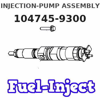
Information injection-pump assembly
BOSCH
9 460 614 559
9460614559
ZEXEL
104745-9300
1047459300
NISSAN
167005T112
167005t112
Rating:
Cross reference number
BOSCH
9 460 614 559
9460614559
ZEXEL
104745-9300
1047459300
NISSAN
167005T112
167005t112
Zexel num
Bosch num
Firm num
Name
104745-9300
9 460 614 559
167005T112 NISSAN
INJECTION-PUMP ASSEMBLY
TD25 * K
TD25 * K
104745-9300
9 460 614 559
167005T112 NISSAN-DIESEL
INJECTION-PUMP ASSEMBLY
TD25 * K
TD25 * K
Calibration Data:
Adjustment conditions
Test oil
1404 Test oil ISO4113orSAEJ967d
1404 Test oil ISO4113orSAEJ967d
Test oil temperature
degC
45
45
50
Nozzle
105780-0060
Bosch type code
NP-DN0SD1510
Nozzle holder
105780-2150
Opening pressure
MPa
13
13
13.3
Opening pressure
kgf/cm2
133
133
136
Injection pipe
157805-7320
Injection pipe
Inside diameter - outside diameter - length (mm) mm 2-6-450
Inside diameter - outside diameter - length (mm) mm 2-6-450
Joint assembly
157641-4720
Tube assembly
157641-4020
Transfer pump pressure
kPa
20
20
20
Transfer pump pressure
kgf/cm2
0.2
0.2
0.2
Direction of rotation (viewed from drive side)
Right R
Right R
Injection timing adjustment
Pump speed
r/min
1100
1100
1100
Average injection quantity
mm3/st.
42.1
41.6
42.6
Difference in delivery
mm3/st.
3
Basic
*
Oil temperature
degC
50
48
52
Injection timing adjustment_02
Pump speed
r/min
600
600
600
Average injection quantity
mm3/st.
39.5
37
42
Oil temperature
degC
50
48
52
Injection timing adjustment_03
Pump speed
r/min
1100
1100
1100
Average injection quantity
mm3/st.
42.1
41.1
43.1
Difference in delivery
mm3/st.
3.5
Basic
*
Oil temperature
degC
50
48
52
Injection timing adjustment_04
Pump speed
r/min
2150
2150
2150
Average injection quantity
mm3/st.
41
38
44
Oil temperature
degC
52
50
54
Injection quantity adjustment
Pump speed
r/min
2350
2350
2350
Average injection quantity
mm3/st.
34.3
32.3
36.3
Basic
*
Oil temperature
degC
52
50
54
Injection quantity adjustment_02
Pump speed
r/min
2700
2700
2700
Average injection quantity
mm3/st.
3
Oil temperature
degC
55
52
58
Injection quantity adjustment_03
Pump speed
r/min
2350
2350
2350
Average injection quantity
mm3/st.
34.3
31.8
36.8
Basic
*
Oil temperature
degC
52
50
54
Injection quantity adjustment_04
Pump speed
r/min
2550
2550
2550
Average injection quantity
mm3/st.
11.8
7.3
16.3
Oil temperature
degC
55
52
58
Governor adjustment
Pump speed
r/min
350
350
350
Average injection quantity
mm3/st.
7.2
5.2
9.2
Difference in delivery
mm3/st.
2
Basic
*
Oil temperature
degC
48
46
50
Governor adjustment_02
Pump speed
r/min
350
350
350
Average injection quantity
mm3/st.
7.2
4.7
9.7
Difference in delivery
mm3/st.
2.5
Basic
*
Oil temperature
degC
48
46
50
Timer adjustment
Pump speed
r/min
100
100
100
Average injection quantity
mm3/st.
60
50
80
Basic
*
Oil temperature
degC
48
46
50
Remarks
Full
Full
Timer adjustment_02
Pump speed
r/min
100
100
100
Average injection quantity
mm3/st.
60
45
80
Oil temperature
degC
48
46
50
Remarks
Full
Full
Speed control lever angle
Pump speed
r/min
350
350
350
Average injection quantity
mm3/st.
0
0
0
Oil temperature
degC
48
46
50
Remarks
Magnet OFF at idling position
Magnet OFF at idling position
0000000901
Pump speed
r/min
1100
1100
1100
Overflow quantity
cm3/min
390
260
520
Oil temperature
degC
50
48
52
Stop lever angle
Pump speed
r/min
1100
1100
1100
Pressure
kPa
431
402
460
Pressure
kgf/cm2
4.4
4.1
4.7
Basic
*
Oil temperature
degC
50
48
52
Stop lever angle_02
Pump speed
r/min
1100
1100
1100
Pressure
kPa
431
392
470
Pressure
kgf/cm2
4.4
4
4.8
Basic
*
Oil temperature
degC
50
48
52
Stop lever angle_03
Pump speed
r/min
1700
1700
1700
Pressure
kPa
579
540
618
Pressure
kgf/cm2
5.9
5.5
6.3
Oil temperature
degC
50
48
52
0000001101
Pump speed
r/min
1100
1100
1100
Timer stroke
mm
2.6
2.4
2.8
Basic
*
Oil temperature
degC
50
48
52
_02
Pump speed
r/min
700
700
700
Timer stroke
mm
0.5
0.5
Oil temperature
degC
50
48
52
_03
Pump speed
r/min
1100
1100
1100
Timer stroke
mm
2.6
2.3
2.9
Basic
*
Oil temperature
degC
50
48
52
_04
Pump speed
r/min
1700
1700
1700
Timer stroke
mm
4.9
4.4
5.4
Oil temperature
degC
50
48
52
_05
Pump speed
r/min
2550
2550
2550
Timer stroke
mm
7.4
6.9
7.8
Oil temperature
degC
55
52
58
0000001201
Max. applied voltage
V
8
8
8
Test voltage
V
13
12
14
0000001501
Pump speed
r/min
1100
1100
1100
Height
m
2000
2000
2000
Atmospheric pressure difference
kPa
-21.9
-21.9
-21.9
Atmospheric pressure difference
mmHg
-164
-164
-164
Average injection quantity
mm3/st.
33.1
31.6
34.6
Decrease qty
mm3/st.
9
9
9
Decrease rate
%
21
21
21
Basic
*
Oil temperature
degC
50
48
52
_02
Pump speed
r/min
1000
1000
1000
Height
m
0
0
0
Atmospheric pressure difference
kPa
0
0
0
Atmospheric pressure difference
mmHg
0
0
0
Average injection quantity
mm3/st.
42.1
41.1
43.1
Oil temperature
degC
50
48
52
_03
Pump speed
r/min
1000
1000
1000
Height
m
500
500
500
Atmospheric pressure difference
kPa
-5.9
-9.2
-2.6
Atmospheric pressure difference
mmHg
-44
-69
-19
Average injection quantity
mm3/st.
42.1
42.1
42.1
Oil temperature
degC
50
48
52
_04
Pump speed
r/min
1000
1000
1000
Height
m
2000
2000
2000
Atmospheric pressure difference
kPa
-21.9
-21.9
-21.9
Atmospheric pressure difference
mmHg
-164
-164
-164
Average injection quantity
mm3/st.
33.1
31.1
35.1
Oil temperature
degC
50
48
52
_05
Pump speed
r/min
1000
1000
1000
Height
m
4000
4000
4000
Atmospheric pressure difference
kPa
-39.7
-39.7
-39.7
Atmospheric pressure difference
mmHg
-298
-298
-298
Average injection quantity
mm3/st.
26.2
26.2
26.2
Oil temperature
degC
50
48
52
Timing setting
K dimension
mm
3.3
3.2
3.4
KF dimension
mm
5.8
5.7
5.9
MS dimension
mm
0.9
0.8
1
Pre-stroke
mm
0.1
0.08
0.12
Control lever angle alpha
deg.
25
21
29
Control lever angle beta
deg.
36
31
41
Information:
WATER SLEEVE CLAMP
1. Clamp.3. Use water sleeve tool (2) to move water sleeve (3) into front cover.4. Remove the cylinder head retaining bolts (4) and (5).
MOVING WATER SLEEVE
2. 8S6692 Water Sleeve Tool. 3. Water sleeve.
CYLINDER HEAD
4. Bolts (four each head). 5. Bolts (eighteen each head).
Be sure fuel injection nozzles are removed before removing head. Nozzles extend through the head and nozzle tips can be broken off if nozzles are not removed from the head.
5. Install two 1P7407 Lifting Eye Bolts in the cylinder head. Attach a hoist and remove the cylinder head assembly, the weight is approx. 85 lbs. (39 kg).
REMOVING CYLINDER HEADInstall Cylinder Head Assemblies
1. Clean the mating surfaces of the cylinder head and cylinder block. Install new cylinder head gasket, clean and dry. Clean bores in cylinder head and inspect and lubricate O-rings for water sleeves.2. Install two 1P7407 Lifting Eye Bolts in the cylinder head. Attach a hoist and install the cylinder head assembly. Coat the cylinder head retaining bolt threads with 9M3710 Anti-Seize Compound. Install the bolts and tighten in the following Step sequence. Step A: Tighten bolts 1 through 18 in numerical order to 60 10 lb. ft. (8.3 1.4 mkg).Step B: Retighten bolts 1 through 18 in numerical order to 95 5 lb. ft. (13.1 0.7 mkg).Step C: Finally tighten bolts 1 through 18 in numerical order (hand tighten only) to 95 5 lb. ft. (13.1 0.7 mkg).Step D: Tighten bolts 19, 20, 21, and 22 in numerical order to 32 5 lb. ft. (4.4 0.7 mkg).
CYLINDER HEAD BOLT LOCATION3. Use the 8S6692 Water Sleeve Tool to slide water sleeve into cylinder head and install clamp.Disassemble Cylinder Head
1. Place head on the FT806 Cylinder Head Bench or the 8S6691 Cylinder Head Stand. Use FT967 Adapter Plates to mount head on the FT806 Cylinder Head Bench.2. Use a 5S1330 or 7F4291 Valve Spring Compressor (1) to remove the valves and valve springs.
REMOVING VALVES
1. 5S1330 Valve Spring Compressor illustrated.3. Use the 8S2263 Valve Spring Tester to check valve spring tension.4. The exhaust valve seats have replaceable inserts. To remove, use the 8S7170 Valve Seat Insert Puller Group.
REMOVING EXHAUST VALVE SEAT INSERTS The valve guides are cast in the cylinder head. If the guides show wear or bellmouthing, they can be restored to original tolerances through knurling.Assemble Cylinder Head
1. Lubricate valve stems with clean engine oil (SAE 30) before installing valves into cylinder head. Earlier engines use a valve spring retainer and washer combination instead of the one piece valve spring retainer shown.
CYLINDER HEAD
Have questions with 104745-9300?
Group cross 104745-9300 ZEXEL
Nissan
104745-9300
9 460 614 559
167005T112
INJECTION-PUMP ASSEMBLY
TD25
TD25
Nissan-Diesel
104745-9300
9 460 614 559
167005T112
INJECTION-PUMP ASSEMBLY
TD25
TD25