Information injection-pump assembly
BOSCH
9 460 611 965
9460611965
ZEXEL
104745-9172
1047459172
NISSAN-DIESEL
1670086P02
1670086p02
Rating:
Components :
| 0. | INJECTION-PUMP ASSEMBLY | 104745-9172 |
| 1. | _ | |
| 2. | FUEL INJECTION PUMP | 104645-9172 |
| 3. | NUMBER PLATE | 146958-3600 |
| 4. | _ | |
| 5. | CAPSULE | |
| 6. | ADJUSTING DEVICE | |
| 7. | NOZZLE AND HOLDER ASSY | 105148-1221 |
| 8. | Nozzle and Holder | 16600-63G01 |
| 9. | Open Pre:MPa(Kqf/cm2) | 9.8{100} |
| 10. | NOZZLE-HOLDER | 105078-0050 |
| 11. | NOZZLE | 105007-1210 |
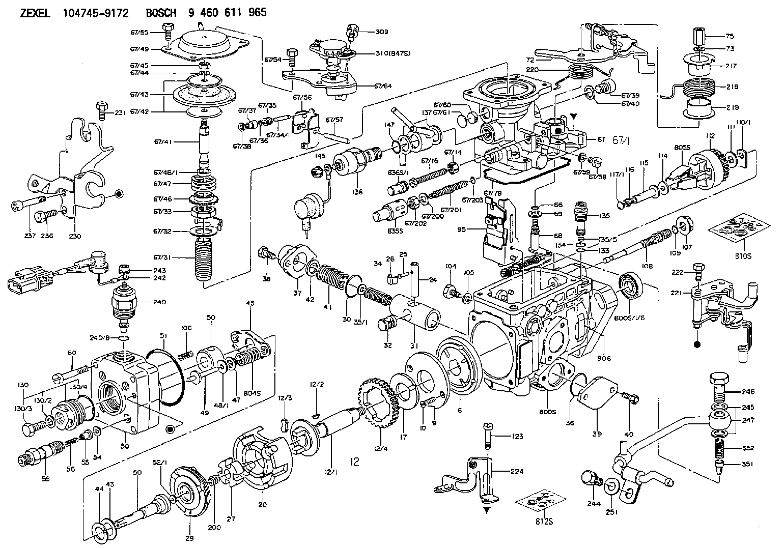
Scheme ###:
| 1/6. | [1] | 146601-0900 | PACKING RING |
| 6. | [1] | 146100-0420 | SUPPLY PUMP |
| 9. | [1] | 146103-0100 | COVER |
| 10. | [2] | 139104-0000 | FLAT-HEAD SCREW |
| 12. | [1] | 146200-0020 | DRIVE SHAFT |
| 12/1. | [1] | 146200-0000 | DRIVE SHAFT |
| 12/2. | [1] | 146201-0000 | WOODRUFF KEY |
| 12/3. | [2] | 146202-0100 | DAMPER |
| 12/4. | [1] | 146203-0000 | TOOTHED GEAR |
| 17. | [1] | 146204-0000 | PLAIN WASHER |
| 20. | [1] | 146210-2320 | ROLLER SET |
| 24. | [1] | 146303-0000 | BEARING PIN |
| 25. | [1] | 146304-0000 | BEARING PIN |
| 26. | [1] | 146305-0000 | CLAMPING BAND |
| 27. | [1] | 146205-0000 | SLOTTED WASHER |
| 29. | [1] | 146220-4320 | CAM PLATE |
| 30. | [1] | 146600-0800 | O-RING |
| 31. | [1] | 146311-6120 | PUMP PLUNGER |
| 32. | [1] | 146301-0000 | SLIDING PIECE |
| 34. | [1] | 146312-4300 | COMPRESSION SPRING |
| 34B. | [1] | 146312-5400 | COMPRESSION SPRING |
| 34C. | [1] | 146312-3200 | COMPRESSION SPRING |
| 35/1. | [1] | 146690-3200 | SHIM D11.5&9.4T0.1 |
| 35/1. | [1] | 146690-3300 | SHIM D11.5&9.4T0.2 |
| 35/1. | [1] | 146690-3400 | SHIM D11.5&9.4T0.25 |
| 35/1. | [1] | 146690-3500 | SHIM D11.5&9.4T1.0 |
| 35/1. | [1] | 146690-4100 | SHIM D11.5&9.4T2 |
| 35/1. | [1] | 146690-4200 | SHIM D11.5&9.4T0.5 |
| 35/1. | [1] | 146690-4300 | SHIM D11.5&9.4T0.75 |
| 36. | [1] | 146600-0800 | O-RING |
| 37. | [1] | 146310-1600 | COVER |
| 38. | [2] | 146620-5000 | BLEEDER SCREW |
| 39. | [1] | 146310-0100 | COVER |
| 40. | [2] | 146620-5000 | BLEEDER SCREW |
| 41. | [1] | 146312-1900 | COMPRESSION SPRING |
| 42. | [1] | 146602-8500 | PLAIN WASHER |
| 43. | [1] | 146230-0000 | SHIM |
| 44. | [1] | 146230-0100 | PLAIN WASHER |
| 45. | [1] | 146231-0001 | SLOTTED WASHER |
| 47. | [2] | 146233-0000 | SLOTTED WASHER |
| 48/1. | [1] | 146603-0000 | SHIM D17.0&5.2T0.50 |
| 48/1. | [1] | 146603-0100 | SHIM D17.0&5.2T0.80 |
| 48/1. | [1] | 146603-0200 | SHIM D17.0&5.2T1.00 |
| 48/1. | [1] | 146603-0300 | SHIM D17.0&5.2T1.20 |
| 48/1. | [1] | 146603-0400 | SHIM D17.0&5.2T1.50 |
| 48/1. | [1] | 146603-0500 | SHIM D17.0&5.2T1.80 |
| 48/1. | [1] | 146603-0600 | SHIM D17.0&5.2T2.00 |
| 48/1. | [1] | 146690-1400 | SHIM D17&5.2T0.9 |
| 48/1. | [1] | 146690-1500 | SHIM D17&5.2T1.1 |
| 48/1. | [1] | 146690-1600 | SHIM D17&5.2T1.3 |
| 48/1. | [1] | 146690-1700 | SHIM D17&5.2T1.4 |
| 48/1. | [1] | 146690-1800 | SHIM D17&5.2T1.6 |
| 48/1. | [1] | 146690-1900 | SHIM D17&5.2T1.7 |
| 48/1. | [1] | 146690-5800 | SHIM |
| 48/1. | [1] | 146690-5900 | SHIM |
| 48/1. | [1] | 146690-6000 | SHIM |
| 48/1. | [1] | 146690-6100 | SHIM |
| 48/1. | [1] | 146690-6200 | SHIM |
| 48/1. | [1] | 146690-6300 | SHIM |
| 48/1. | [1] | 146690-6400 | SHIM |
| 48/1. | [1] | 146690-6500 | SHIM |
| 48/1. | [1] | 146690-6600 | SHIM |
| 48/1. | [1] | 146690-6700 | SHIM |
| 48/1. | [1] | 146690-6800 | SHIM |
| 48/1. | [1] | 146690-6900 | SHIM |
| 48/1. | [1] | 146690-7000 | SHIM |
| 48/1. | [1] | 146690-7100 | SHIM |
| 48/1. | [1] | 146690-7200 | SHIM |
| 48/1. | [1] | 146690-7300 | SHIM |
| 48/1. | [1] | 146690-7400 | SHIM |
| 48/1. | [1] | 146690-7500 | SHIM |
| 48/1. | [1] | 146690-7800 | SHIM |
| 49. | [2] | 146234-0120 | GUIDE PIN |
| 50. | [1] | 146401-4020 | HYDRAULIC HEAD |
| 50. | [1] | 146401-4020 | HYDRAULIC HEAD |
| 50. | [1] | 146401-4020 | HYDRAULIC HEAD |
| 51. | [1] | 146600-0000 | O-RING |
| 52/1. | [1] | 146420-0000 | SHIM D9.5&3.0T1.90 |
| 52/1. | [1] | 146420-0100 | SHIM D9.5&3.0T1.92 |
| 52/1. | [1] | 146420-0200 | SHIM D9.5&3.0T1.94 |
| 52/1. | [1] | 146420-0300 | SHIM D9.5&3.0T1.96 |
| 52/1. | [1] | 146420-0400 | SHIM D9.5&3.0T1.98 |
| 52/1. | [1] | 146420-0500 | SHIM D9.5&3.0T2.00 |
| 52/1. | [1] | 146420-0600 | SHIM D9.5&3.0T2.02 |
| 52/1. | [1] | 146420-0700 | SHIM D9.5&3.0T2.04 |
| 52/1. | [1] | 146420-0800 | SHIM D9.5&3.0T2.06 |
| 52/1. | [1] | 146420-0900 | SHIM D9.5&3.0T2.08 |
| 52/1. | [1] | 146420-1000 | SHIM D9.5&3.0T2.10 |
| 52/1. | [1] | 146420-1100 | SHIM D9.5&3.0T2.12 |
| 52/1. | [1] | 146420-1200 | SHIM D9.5&3.0T2.14 |
| 52/1. | [1] | 146420-1300 | SHIM D9.5&3.0T2.16 |
| 52/1. | [1] | 146420-1400 | SHIM D9.5&3.0T2.18 |
| 52/1. | [1] | 146420-1500 | SHIM D9.5&3.0T2.20 |
| 52/1. | [1] | 146420-1600 | SHIM D9.5&3.0T2.22 |
| 52/1. | [1] | 146420-1700 | SHIM D9.5&3.0T2.24 |
| 52/1. | [1] | 146420-1800 | SHIM D9.5&3.0T2.26 |
| 52/1. | [1] | 146420-1900 | SHIM D9.5&3.0T2.28 |
| 52/1. | [1] | 146420-2000 | SHIM D9.5&3.0T2.30 |
| 52/1. | [1] | 146420-2100 | SHIM D9.5&3.0T2.32 |
| 52/1. | [1] | 146420-2200 | SHIM D9.5&3.0T2.34 |
| 52/1. | [1] | 146420-2300 | SHIM D9.5&3.0T2.36 |
| 52/1. | [1] | 146420-2400 | SHIM D9.5&3.0T2.38 |
| 52/1. | [1] | 146420-2500 | SHIM D9.5&3.0T2.40 |
| 52/1. | [1] | 146420-2600 | SHIM D9.5&3.0T2.42 |
| 52/1. | [1] | 146420-2700 | SHIM D9.5&3.0T2.44 |
| 52/1. | [1] | 146420-2800 | SHIM D9.5&3.0T2.46 |
| 52/1. | [1] | 146420-2900 | SHIM D9.5&3.0T2.48 |
| 52/1. | [1] | 146420-3000 | SHIM D9.5&3.0T2.50 |
| 52/1. | [1] | 146420-3100 | SHIM D9.5&3.0T2.52 |
| 52/1. | [1] | 146420-3200 | SHIM D9.5&3.0T2.54 |
| 52/1. | [1] | 146420-3300 | SHIM D9.5&3.0T2.56 |
| 52/1. | [1] | 146420-3400 | SHIM D9.5&3.0T2.58 |
| 52/1. | [1] | 146420-3500 | SHIM D9.5&3.0T2.60 |
| 52/1. | [1] | 146420-3600 | SHIM D9.5&3.0T2.62 |
| 52/1. | [1] | 146420-3700 | SHIM D9.5&3.0T2.64 |
| 52/1. | [1] | 146420-3800 | SHIM D9.5&3.0T2.66 |
| 52/1. | [1] | 146420-3900 | SHIM D9.5&3.0T2.68 |
| 52/1. | [1] | 146420-4000 | SHIM D9.5&3.0T2.70 |
| 52/1. | [1] | 146420-4100 | SHIM D9.5&3.0T2.72 |
| 52/1. | [1] | 146420-4200 | SHIM D9.5&3.0T2.74 |
| 52/1. | [1] | 146420-4300 | SHIM D9.5&3.0T2.76 |
| 52/1. | [1] | 146420-4400 | SHIM D9.5&3.0T2.78 |
| 52/1. | [1] | 146420-4500 | SHIM D9.5&3.0T2.80 |
| 52/1. | [1] | 146420-4600 | SHIM D9.5&3.0T2.82 |
| 52/1. | [1] | 146420-4700 | SHIM D9.5&3.0T2.84 |
| 52/1. | [1] | 146420-4800 | SHIM D9.5&3.0T2.86 |
| 52/1. | [1] | 146420-4900 | SHIM D9.5&3.0T2.88 |
| 52/1. | [1] | 146420-5000 | SHIM D9.5&3.0T2.90 |
| 52/1. | [1] | 146420-5100 | SHIM D9.5&3.0T1.74 |
| 52/1. | [1] | 146420-5200 | SHIM D9.5&3.0T1.76 |
| 52/1. | [1] | 146420-5300 | SHIM D9.5&3.0T1.78 |
| 52/1. | [1] | 146420-5400 | SHIM D9.5&3.0T1.80 |
| 52/1. | [1] | 146420-5500 | SHIM D9.5&3.0T1.82 |
| 52/1. | [1] | 146420-5600 | SHIM D9.5&3.0T1.84 |
| 52/1. | [1] | 146420-5700 | SHIM D9.5&3.0T1.86 |
| 52/1. | [1] | 146420-5800 | SHIM D9.5&3.0T1.88 |
| 54. | [4] | 146433-0100 | GASKET D12&6.4T1.00 |
| 55. | [4] | 146430-2920 | DELIVERY-VALVE ASSEMBLY |
| 56. | [4] | 146432-0000 | COMPRESSION SPRING |
| 58. | [4] | 146440-0220 | FITTING |
| 60. | [3] | 139106-0100 | FLAT-HEAD SCREW |
| 66. | [1] | 146600-0100 | O-RING |
| 67. | [1] | 146752-9420 | MANIFOLD-PRESSURE COMP. |
| 67/1. | [1] | 146805-3320 | GOVERNOR COVER |
| 67/14. | [1] | 146621-1700 | UNION NUT |
| 67/16. | [1] | 146526-3000 | BLEEDER SCREW |
| 67/31. | [1] | 146710-0800 | BUSHING |
| 67/32. | [1] | 146711-0000 | PLATE |
| 67/33. | [1] | 139218-0400 | UNION NUT |
| 67/34. | [1] | 146712-1700 | BEARING PIN |
| 67/35. | [1] | 146621-0300 | UNION NUT |
| 67/36. | [1] | 146600-1400 | O-RING |
| 67/37. | [1] | 146710-1400 | BUSHING |
| 67/38. | [1] | 139506-0200 | GASKET D8.9&6.8T1.00 |
| 67/39. | [1] | 146620-0300 | CAPSULE |
| 67/40. | [1] | 026512-1540 | GASKET D15.4&12.2T1.50 |
| 67/41. | [1] | 146713-4100 | ADJUSTING PIN |
| 67/42. | [2] | 146714-0000 | PLATE |
| 67/43. | [1] | 146715-0000 | DIAPHRAGM |
| 67/44. | [1] | 139306-0100 | LOCKING WASHER |
| 67/45. | [1] | 013030-6040 | UNION NUT M6P1H3.6 |
| 67/46. | [1] | 146716-0000 | UNION NUT |
| 67/47. | [1] | 146717-1400 | COILED SPRING |
| 67/48/1. | [1] | 146720-0000 | SPACER BUSHING L3.7 |
| 67/48/1. | [1] | 146720-0100 | SPACER BUSHING L3.9 |
| 67/48/1. | [1] | 146720-0200 | SPACER BUSHING L4.1 |
| 67/48/1. | [1] | 146720-0300 | SPACER BUSHING L4.3 |
| 67/48/1. | [1] | 146720-0400 | SPACER BUSHING L4.5 |
| 67/48/1. | [1] | 146720-0500 | SPACER BUSHING L4.7 |
| 67/48/1. | [1] | 146720-0600 | SPACER BUSHING L4.9 |
| 67/48/1. | [1] | 146720-0700 | SPACER BUSHING L5.1 |
| 67/48/1. | [1] | 146720-0800 | SPACER BUSHING L5.3 |
| 67/48/1. | [1] | 146720-0900 | SPACER BUSHING L2.7 |
| 67/48/1. | [1] | 146720-1000 | SPACER BUSHING L2.9 |
| 67/48/1. | [1] | 146720-1100 | SPACER BUSHING L3.1 |
| 67/48/1. | [1] | 146720-1200 | SPACER BUSHING L3.3 |
| 67/48/1. | [1] | 146720-1300 | SPACER BUSHING L3.5 |
| 67/48/1. | [1] | 146720-1400 | SPACER BUSHING L2.8 |
| 67/48/1. | [1] | 146720-1500 | SPACER BUSHING L3.0 |
| 67/48/1. | [1] | 146720-1600 | SPACER BUSHING L3.2 |
| 67/48/1. | [1] | 146720-1700 | SPACER BUSHING L3.4 |
| 67/48/1. | [1] | 146720-1800 | SPACER BUSHING L3.6 |
| 67/48/1. | [1] | 146720-1900 | SPACER BUSHING L3.8 |
| 67/48/1. | [1] | 146720-2000 | SPACER BUSHING L4.0 |
| 67/48/1. | [1] | 146720-2100 | SPACER BUSHING L4.2 |
| 67/48/1. | [1] | 146720-2200 | SPACER BUSHING L4.4 |
| 67/48/1. | [1] | 146720-2300 | SPACER BUSHING L4.6 |
| 67/48/1. | [1] | 146720-2400 | SPACER BUSHING L4.8 |
| 67/48/1. | [1] | 146720-2500 | SPACER BUSHING L5.0 |
| 67/48/1. | [1] | 146720-2600 | SPACER BUSHING L5.2 |
| 67/48/1. | [1] | 146720-2700 | SPACER BUSHING L5.4 |
| 67/48/1. | [1] | 146720-2800 | SPACER BUSHING L5.5 |
| 67/48/1. | [1] | 146720-2900 | SPACER BUSHING L5.6 |
| 67/48/1. | [1] | 146720-4500 | SPACER BUSHING L1.8 |
| 67/48/1. | [1] | 146720-4600 | SPACER BUSHING L1.9 |
| 67/48/1. | [1] | 146720-4700 | SPACER BUSHING L2.0 |
| 67/48/1. | [1] | 146720-4800 | SPACER BUSHING L2.1 |
| 67/48/1. | [1] | 146720-4900 | SPACER BUSHING L2.2 |
| 67/48/1. | [1] | 146720-5000 | SPACER BUSHING L2.3 |
| 67/48/1. | [1] | 146720-5100 | SPACER BUSHING L2.4 |
| 67/48/1. | [1] | 146720-5200 | SPACER BUSHING L2.5 |
| 67/48/1. | [1] | 146720-5300 | SPACER BUSHING L2.6 |
| 67/48/1. | [1] | 146725-2500 | SPACER BUSHING L5.7 |
| 67/48/1. | [1] | 146725-2600 | SPACER BUSHING L5.8 |
| 67/48/1. | [1] | 146725-2700 | SPACER BUSHING L5.9 |
| 67/48/1. | [1] | 146725-2800 | SPACER BUSHING L6.0 |
| 67/48/1. | [1] | 146725-2900 | SPACER BUSHING L6.1 |
| 67/48/1. | [1] | 146725-3000 | SPACER BUSHING L6.2 |
| 67/48/1. | [1] | 146725-3100 | SPACER BUSHING L6.3 |
| 67/48/1. | [1] | 146725-3200 | SPACER BUSHING L6.4 |
| 67/48/1. | [1] | 146725-3300 | SPACER BUSHING L6.5 |
| 67/48/1. | [1] | 146725-3400 | SPACER BUSHING L6.6 |
| 67/48/1. | [1] | 146725-3500 | SPACER BUSHING L6.7 |
| 67/48/1. | [1] | 146725-3600 | SPACER BUSHING L6.8 |
| 67/48/1. | [1] | 146725-3700 | SPACER BUSHING L6.9 |
| 67/48/1. | [1] | 146725-3800 | SPACER BUSHING L7.0 |
| 67/48/1. | [1] | 146725-3900 | SPACER BUSHING L7.1 |
| 67/48/1. | [1] | 146725-4000 | SPACER BUSHING L7.2 |
| 67/48/1. | [1] | 146725-4100 | SPACER BUSHING L7.3 |
| 67/48/1. | [1] | 146725-4200 | SPACER BUSHING L7.4 |
| 67/48/1. | [1] | 146725-4300 | SPACER BUSHING L7.5 |
| 67/49. | [1] | 146721-3220 | COVER |
| 67/54. | [2] | 139006-4600 | BLEEDER SCREW |
| 67/55. | [2] | 139006-4500 | BLEEDER SCREW |
| 67/56. | [1] | 146723-0200 | CONTROL LEVER |
| 67/57. | [1] | 146712-0100 | BEARING PIN |
| 67/58. | [2] | 146620-0600 | CAPSULE |
| 67/59. | [2] | 026506-1040 | GASKET D9.9&6.2T1 |
| 67/60. | [1] | 146724-0300 | ELEMENT |
| 67/61. | [1] | 146724-0600 | CAPSULE |
| 67/64. | [1] | 146927-2300 | BRACKET |
| 67/78. | [1] | 146600-4400 | SEAL RING |
| 67/200. | [1] | 139308-0300 | PLAIN WASHER |
| 67/201. | [1] | 146545-3400 | THREADED PIN L53.00 |
| 67/201B. | [1] | 146545-3500 | THREADED PIN L55.00 |
| 67/201C. | [1] | 146545-3600 | THREADED PIN L57.00 |
| 67/202. | [1] | 139208-0900 | UNION NUT |
| 67/203. | [1] | 146600-1200 | O-RING |
| 68. | [1] | 146810-2120 | CONTROL SHAFT |
| 69. | [1] | 139310-0200 | PLAIN WASHER |
| 72. | [1] | 146536-5320 | CONTROL LEVER |
| 72B. | [1] | 146536-5420 | CONTROL LEVER |
| 72C. | [1] | 146830-6720 | CONTROL LEVER |
| 72D. | [1] | 146830-6820 | CONTROL LEVER |
| 73. | [1] | 014110-6440 | LOCKING WASHER |
| 75. | [1] | 146621-0700 | UNION NUT |
| 95. | [1] | 146851-2920 | FULCRUM LEVER |
| 104. | [2] | 146568-0000 | SLOTTED SPRING PIN |
| 105. | [2] | 026508-1140 | GASKET D11.4&8.2T1 |
| 106. | [2] | 146588-0500 | COILED SPRING |
| 107. | [1] | 146569-0300 | UNION NUT |
| 108. | [1] | 146570-0420 | GOVERNOR SHAFT |
| 109. | [1] | 146600-0400 | O-RING |
| 110/1. | [1] | 146571-0000 | SHIM D20.2&8.3T1.05 |
| 110/1. | [1] | 146571-0100 | SHIM D20.2&8.3T1.25 |
| 110/1. | [1] | 146571-0200 | SHIM D20.2&8.3T1.45 |
| 110/1. | [1] | 146571-0300 | SHIM D20.2&8.3T1.65 |
| 110/1. | [1] | 146571-0400 | SHIM D20.2&8.3T1.85 |
| 110/1. | [1] | 146571-0500 | SHIM D20.2&8.3T1.15 |
| 110/1. | [1] | 146571-0600 | SHIM D20.2&8.3T1.35 |
| 110/1. | [1] | 146571-0700 | SHIM D20.2&8.3T1.55 |
| 110/1. | [1] | 146571-0800 | SHIM D20.2&8.3T1.75 |
| 111. | [1] | 146602-0600 | PLAIN WASHER D20&8.4T1.40 |
| 112. | [1] | 146572-0020 | FLYWEIGHT ASSEMBLY |
| 114. | [1] | 146602-0500 | PLAIN WASHER D17&6.4T1.60 |
| 115. | [1] | 146575-7500 | SLIDING SLEEVE |
| 116. | [1] | 146576-0200 | CAP |
| 117/1. | [1] | 146577-1800 | PLUG L2.10 |
| 117/1. | [1] | 146577-1900 | PLUG L2.30 |
| 117/1. | [1] | 146577-2000 | PLUG L2.50 |
| 117/1. | [1] | 146577-2100 | PLUG L2.70 |
| 117/1. | [1] | 146577-2200 | PLUG L2.90 |
| 117/1. | [1] | 146577-2300 | PLUG L3.10 |
| 117/1. | [1] | 146577-2400 | PLUG L3.30 |
| 117/1. | [1] | 146577-2500 | PLUG L3.50 |
| 117/1. | [1] | 146577-2600 | PLUG L3.70 |
| 117/1. | [1] | 146577-2700 | PLUG L3.90 |
| 117/1. | [1] | 146577-2800 | PLUG L4.10 |
| 117/1. | [1] | 146577-2900 | PLUG L4.30 |
| 117/1. | [1] | 146577-3000 | PLUG L4.50 |
| 117/1. | [1] | 146577-3100 | PLUG L4.70 |
| 117/1. | [1] | 146577-3200 | PLUG L4.90 |
| 117/1. | [1] | 146577-3300 | PLUG L5.10 |
| 117/1. | [1] | 146577-6700 | PLUG L2.2 |
| 117/1. | [1] | 146577-6800 | PLUG L2.4 |
| 117/1. | [1] | 146577-6900 | PLUG L2.6 |
| 117/1. | [1] | 146577-7000 | PLUG L2.8 |
| 117/1. | [1] | 146577-7100 | PLUG L3.0 |
| 117/1. | [1] | 146577-7200 | PLUG L3.2 |
| 117/1. | [1] | 146577-7300 | PLUG L3.4 |
| 117/1. | [1] | 146577-7400 | PLUG L3.6 |
| 117/1. | [1] | 146577-7500 | PLUG L3.8 |
| 117/1. | [1] | 146577-7600 | PLUG L4.0 |
| 117/1. | [1] | 146577-7700 | PLUG L4.2 |
| 117/1. | [1] | 146577-7800 | PLUG L4.4 |
| 117/1. | [1] | 146577-7900 | PLUG L4.6 |
| 117/1. | [1] | 146577-8000 | PLUG L4.8 |
| 117/1. | [1] | 146577-8100 | PLUG L5.0 |
| 117/1. | [1] | 146877-0000 | PLUG L5.2 |
| 117/1. | [1] | 146877-0100 | PLUG L5.3 |
| 117/1. | [1] | 146877-0200 | PLUG L5.4 |
| 117/1. | [1] | 146877-0300 | PLUG L5.5 |
| 117/1. | [1] | 146877-4700 | PLUG |
| 117/1. | [1] | 146877-4800 | PLUG |
| 117/1. | [1] | 146877-4900 | PLUG |
| 117/1. | [1] | 146877-5000 | PLUG |
| 123. | [4] | 146620-0500 | HEX-SOCKET-HEAD CAP SCREW |
| 130. | [1] | 146421-0020 | CAPSULE |
| 130/2. | [1] | 026508-1140 | GASKET D11.4&8.2T1 |
| 130/3. | [1] | 146422-0000 | BLEEDER SCREW |
| 130/4. | [1] | 146600-0500 | O-RING |
| 133. | [1] | 146600-0600 | O-RING |
| 134. | [1] | 146600-0700 | O-RING |
| 135. | [1] | 146110-0920 | CONTROL VALVE |
| 135/5. | [1] | 146114-0000 | SPRING WASHER |
| 136. | [1] | 146650-5820 | PULLING ELECTROMAGNET |
| 137. | [2] | 139514-0200 | GASKET |
| 145. | [1] | 146621-1000 | UNION NUT |
| 147. | [1] | 016520-1210 | O-RING |
| 200. | [1] | 146206-0100 | COILED SPRING |
| 217. | [1] | 146541-3100 | SLOTTED WASHER |
| 218. | [1] | 146592-6100 | COILED SPRING |
| 219. | [1] | 146541-3000 | BUSHING |
| 220. | [1] | 146592-6000 | COILED SPRING |
| 221. | [1] | 146927-2620 | BRACKET |
| 222. | [2] | 139006-4600 | BLEEDER SCREW |
| 224. | [1] | 146927-2700 | BRACKET |
| 230. | [1] | 146926-4220 | BRACKET |
| 231. | [1] | 139006-4600 | BLEEDER SCREW |
| 236. | [1] | 139006-4800 | BLEEDER SCREW |
| 237. | [1] | 146620-0200 | HEX-SOCKET-HEAD CAP SCREW |
| 240. | [1] | 146650-0720 | PULLING ELECTROMAGNET |
| 240/8. | [1] | 146600-1700 | O-RING |
| 243. | [1] | 146621-1000 | UNION NUT |
| 244. | [1] | 020118-1440 | BLEEDER SCREW |
| 245. | [2] | 026512-1840 | GASKET D17.9&12.2T1.50 |
| 246. | [1] | 027412-2440 | EYE BOLT |
| 247. | [1] | 146665-7620 | PIPE |
| 251. | [1] | 014010-8140 | PLAIN WASHER D18&8.5T1.6 |
| 309. | [1] | 020146-1270 | BLEEDER SCREW |
| 310. | [1] | 146684-6420 | POTENTCIOMETER |
| 351. | [1] | 146125-0101 | FILTER |
| 352. | [1] | 146125-0200 | COILED SPRING |
| 800S. | [1] | 146018-0420 | PUMP HOUSING |
| 800S/1/6. | [1] | 146601-0900 | PACKING RING |
| 800S/1/6. | [1] | 146601-0900 | PACKING RING |
| 804S. | [1] | 146232-0720 | COMPRESSION SPRING |
| 805S. | [1] | 146574-0120 | PARTS SET |
| 810S. | [1] | 146600-1120 | REPAIR SET |
| 812S. | [1] | 146600-1920 | PARTS SET |
| 835S. | [1] | 146598-1000 | CAP |
| 836S/1. | [1] | 146598-0600 | CAP L18 |
| 836S/1. | [1] | 146598-0700 | CAP L21 |
| 836S/1. | [1] | 146598-0800 | CAP L24 |
| 836S/1. | [1] | 146598-0900 | CAP L27 |
| 847S. | [1] | 146684-6410 | POTENTCIOMETER |
| 906. | [1] | 146958-3600 | NAMEPLATE |
Include in #2:
104745-9172
as INJECTION-PUMP ASSEMBLY
Cross reference number
BOSCH
9 460 611 965
9460611965
ZEXEL
104745-9172
1047459172
NISSAN-DIESEL
1670086P02
1670086p02
Zexel num
Bosch num
Firm num
Name
Calibration Data:
Adjustment conditions
Test oil
1404 Test oil ISO4113orSAEJ967d
1404 Test oil ISO4113orSAEJ967d
Test oil temperature
degC
45
45
50
Nozzle
105780-0060
Bosch type code
NP-DN0SD1510
Nozzle holder
105780-2150
Opening pressure
MPa
13
13
13.3
Opening pressure
kgf/cm2
133
133
136
Injection pipe
157805-7320
Injection pipe
Inside diameter - outside diameter - length (mm) mm 2-6-450
Inside diameter - outside diameter - length (mm) mm 2-6-450
Joint assembly
157641-4720
Tube assembly
157641-4020
Transfer pump pressure
kPa
20
20
20
Transfer pump pressure
kgf/cm2
0.2
0.2
0.2
Direction of rotation (viewed from drive side)
Right R
Right R
Injection timing adjustment
Pump speed
r/min
850
850
850
Boost pressure
kPa
32
30.7
33.3
Boost pressure
mmHg
240
230
250
Average injection quantity
mm3/st.
55.4
54.9
55.9
Basic
*
Oil temperature
degC
50
48
52
Remarks
CBS
CBS
Injection timing adjustment_02
Pump speed
r/min
1100
1100
1100
Boost pressure
kPa
66.7
65.4
68
Boost pressure
mmHg
500
490
510
Average injection quantity
mm3/st.
65.2
64.7
65.7
Difference in delivery
mm3/st.
5
Basic
*
Oil temperature
degC
50
48
52
Remarks
Full
Full
Injection timing adjustment_03
Pump speed
r/min
500
500
500
Boost pressure
kPa
0
0
0
Boost pressure
mmHg
0
0
0
Average injection quantity
mm3/st.
48.4
45.4
51.4
Oil temperature
degC
48
46
50
Injection timing adjustment_04
Pump speed
r/min
850
850
850
Boost pressure
kPa
0
0
0
Boost pressure
mmHg
0
0
0
Average injection quantity
mm3/st.
47.4
44.4
50.4
Oil temperature
degC
50
48
52
Injection timing adjustment_05
Pump speed
r/min
850
850
850
Boost pressure
kPa
32
30.7
33.3
Boost pressure
mmHg
240
230
250
Average injection quantity
mm3/st.
55.4
54.4
56.4
Basic
*
Oil temperature
degC
50
48
52
Remarks
CBS
CBS
Injection timing adjustment_06
Pump speed
r/min
1100
1100
1100
Boost pressure
kPa
66.7
65.4
68
Boost pressure
mmHg
500
490
510
Average injection quantity
mm3/st.
65.2
64.2
66.2
Difference in delivery
mm3/st.
5.5
Basic
*
Oil temperature
degC
50
48
52
Remarks
Full
Full
Injection timing adjustment_07
Pump speed
r/min
1500
1500
1500
Boost pressure
kPa
66.7
65.4
68
Boost pressure
mmHg
500
490
510
Average injection quantity
mm3/st.
64
61.5
66.5
Oil temperature
degC
50
48
52
Injection timing adjustment_08
Pump speed
r/min
2000
2000
2000
Boost pressure
kPa
66.7
65.4
68
Boost pressure
mmHg
500
490
510
Average injection quantity
mm3/st.
58.3
55.8
60.8
Oil temperature
degC
50
48
52
Injection quantity adjustment
Pump speed
r/min
2500
2500
2500
Boost pressure
kPa
66.7
65.4
68
Boost pressure
mmHg
500
490
510
Average injection quantity
mm3/st.
23.5
21.5
25.5
Basic
*
Oil temperature
degC
55
52
58
Injection quantity adjustment_02
Pump speed
r/min
2700
2700
2700
Boost pressure
kPa
66.7
65.4
68
Boost pressure
mmHg
500
490
510
Average injection quantity
mm3/st.
10
Oil temperature
degC
55
52
58
Injection quantity adjustment_03
Pump speed
r/min
2250
2250
2250
Boost pressure
kPa
66.7
65.4
68
Boost pressure
mmHg
500
490
510
Average injection quantity
mm3/st.
44.9
40.4
49.4
Oil temperature
degC
52
50
54
Injection quantity adjustment_04
Pump speed
r/min
2500
2500
2500
Boost pressure
kPa
66.7
65.4
68
Boost pressure
mmHg
500
490
510
Average injection quantity
mm3/st.
23.5
20.5
26.5
Basic
*
Oil temperature
degC
55
52
58
Governor adjustment
Pump speed
r/min
400
400
400
Boost pressure
kPa
0
0
0
Boost pressure
mmHg
0
0
0
Average injection quantity
mm3/st.
10.2
8.2
12.2
Difference in delivery
mm3/st.
2
Basic
*
Oil temperature
degC
48
46
50
Governor adjustment_02
Pump speed
r/min
400
400
400
Boost pressure
kPa
0
0
0
Boost pressure
mmHg
0
0
0
Average injection quantity
mm3/st.
10.2
7.7
12.7
Difference in delivery
mm3/st.
2.5
Basic
*
Oil temperature
degC
48
46
50
Timer adjustment
Pump speed
r/min
100
100
100
Boost pressure
kPa
0
0
0
Boost pressure
mmHg
0
0
0
Average injection quantity
mm3/st.
75
60
95
Basic
*
Oil temperature
degC
48
46
50
Remarks
Full
Full
Timer adjustment_02
Pump speed
r/min
100
100
100
Boost pressure
kPa
0
0
0
Boost pressure
mmHg
0
0
0
Average injection quantity
mm3/st.
75
60
95
Oil temperature
degC
48
46
50
Remarks
Full
Full
Speed control lever angle
Pump speed
r/min
350
350
350
Boost pressure
kPa
0
0
0
Boost pressure
mmHg
0
0
0
Average injection quantity
mm3/st.
0
0
0
Oil temperature
degC
48
46
50
Remarks
Magnet OFF at idling position
Magnet OFF at idling position
0000000901
Pump speed
r/min
1100
1100
1100
Boost pressure
kPa
66.7
65.4
68
Boost pressure
mmHg
500
490
510
Overflow quantity with S/T OFF
cm3/min
550
420
680
Oil temperature
degC
50
48
52
Remarks
Without an O-ring
Without an O-ring
_02
Pump speed
r/min
1100
1100
1100
Boost pressure
kPa
66.7
65.4
68
Boost pressure
mmHg
500
490
510
Overflow quantity with S/T OFF
cm3/min
430
300
560
Oil temperature
degC
50
48
52
Remarks
With an O-ring
With an O-ring
Stop lever angle
Pump speed
r/min
1100
1100
1100
Boost pressure
kPa
66.7
65.4
68
Boost pressure
mmHg
500
490
510
Pressure with S/T OFF
kPa
451
431
471
Pressure with S/T OFF
kgf/cm2
4.6
4.4
4.8
Basic
*
Oil temperature
degC
50
48
52
Stop lever angle_02
Pump speed
r/min
1100
1100
1100
Boost pressure
kPa
66.7
65.4
68
Boost pressure
mmHg
500
490
510
Pressure with S/T OFF
kPa
451
412
490
Pressure with S/T OFF
kgf/cm2
4.6
4.2
5
Basic
*
Oil temperature
degC
50
48
52
Stop lever angle_03
Pump speed
r/min
1500
1500
1500
Boost pressure
kPa
66.7
65.4
68
Boost pressure
mmHg
500
490
510
Pressure with S/T OFF
kPa
549
510
588
Pressure with S/T OFF
kgf/cm2
5.6
5.2
6
Oil temperature
degC
50
48
52
0000001101
Pump speed
r/min
1100
1100
1100
Boost pressure
kPa
66.7
65.4
68
Boost pressure
mmHg
500
490
510
Timer stroke with S/T OFF
mm
4.2
4
4.4
Basic
*
Oil temperature
degC
50
48
52
_02
Pump speed
r/min
1100
1100
1100
Boost pressure
kPa
66.7
65.4
68
Boost pressure
mmHg
500
490
510
Timer stroke with S/T ON
mm
6.4
5.9
6.9
Timer stroke with S/T OFF
mm
4.2
3.9
4.5
Basic
*
Oil temperature
degC
50
48
52
_03
Pump speed
r/min
1500
1500
1500
Boost pressure
kPa
66.7
65.4
68
Boost pressure
mmHg
500
490
510
Timer stroke with S/T OFF
mm
6.4
5.9
6.9
Oil temperature
degC
50
48
52
_04
Pump speed
r/min
2000
2000
2000
Boost pressure
kPa
66.7
65.4
68
Boost pressure
mmHg
500
490
510
Timer stroke with S/T OFF
mm
7
6.5
7.4
Oil temperature
degC
50
48
52
0000001201
Max. applied voltage
V
8
8
8
Test voltage
V
13
12
14
0000001401
Pump speed
r/min
1100
1100
1100
Boost pressure
kPa
66.7
65.4
68
Boost pressure
mmHg
500
490
510
Average injection quantity
mm3/st.
44
43.5
44.5
Timer stroke TA
mm
3.6
3.4
3.8
Timer stroke variation dT
mm
0.6
0.6
0.6
Basic
*
Oil temperature
degC
50
48
52
_02
Pump speed
r/min
1100
1100
1100
Boost pressure
kPa
66.7
65.4
68
Boost pressure
mmHg
500
490
510
Average injection quantity
mm3/st.
44
43
45
Timer stroke TA
mm
3.6
3.3
3.9
Basic
*
Oil temperature
degC
50
48
52
_03
Pump speed
r/min
1100
1100
1100
Boost pressure
kPa
66.7
65.4
68
Boost pressure
mmHg
500
490
510
Average injection quantity
mm3/st.
33
30.5
35.5
Timer stroke TA
mm
2.9
2.4
3.4
Oil temperature
degC
50
48
52
Timing setting
K dimension
mm
3.3
3.2
3.4
KF dimension
mm
5.9
5.8
6
MS dimension
mm
1
0.9
1.1
Control lever angle alpha
deg.
10
6
14
Control lever angle beta
deg.
36
31
41
Test data Ex:
0000001801 POTENTIOMETER ADJUSTMENT
Potentiometer adjustment
1. Applied voltage: Vi
2. Boost pressure = P1kPa {P2 mmHg}
3. Set the control lever at the adjusting point. Position the dummy bolt against the lever and fix.
4. Assemble the potentiometer to obtain output voltage V1 (V) at the fixed position.
5. After mounting the potentiometer, remove the dummy bolt.
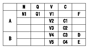
N:Pump speed
Q:Injection quantity
V:Output voltage
A:Performance standards
B:ON, OFF switch standard
C:Angle of the control lever
D:OFF-->ON
E:OFF-->ON
F:Adjusting point
C1:Idle
C2:Full-speed
----------
V1=3.72+-0.03V P1=0kPa P2=0mmHg Vi=10V
----------
N1=850r/min Q1=20.9+-1.0cm3/1,000st V1=3.72+-0.03V V2=(2.18+-0.43)V V3=(8.10+-0.58)V C3=(1.4)deg C4=(15.9)deg P1=0kPa P2=0mmHg Vi=10V
----------
V1=3.72+-0.03V P1=0kPa P2=0mmHg Vi=10V
----------
N1=850r/min Q1=20.9+-1.0cm3/1,000st V1=3.72+-0.03V V2=(2.18+-0.43)V V3=(8.10+-0.58)V C3=(1.4)deg C4=(15.9)deg P1=0kPa P2=0mmHg Vi=10V
Information:
Lubrication System
The lubrication system consists of the oil pump, cooler, filters, internal passages and the oil pan. The pan can be turned end-for-end to provide either a front or rear sump. The dipstick placement and suction tube length correspond with sump location. A longer suction tube and support is required when the pan is positioned for a rear sump.Oil moves through the screen and suction tube to the inlet passage in the oil pump cover. The oil pump cover bolts to the back of the engine front cover. The inlet passage directs oil to the pump.The oil pump is a six lobe, rotor type. The crankshaft gear drives the outer rotor which rotates in a bearing in the front cover. The inner rotor mounts on a stub shaft in the front cover and is driven by the outer rotor.A bypass valve in the pump cover senses pump outlet pressure. The valve opens at approximately 72 psi (5.1 kg/cm2) and bypasses oil back to the inlet side of the pump.Oil from the pump flows through a passage in the front cover to the cylinder block and on to the oil cooler base. The base mounts on the left side of the block. A valve in the base bypasses oil around the cooler when the oil is cold or the oil cooler restriction is higher than the rest of the system. A 14 to 22 psi (0.89 to 1.55 kg/cm2) pressure differential opens the valve.Oil from the cooler flows to two spin on, throw away filters mounted on the oil cooler base. Each filter contains a bypass valve. If the filters become clogged, oil is bypassed around them. An 18 to 20 psi (1.27 to 1.41 kg/cm2) pressure differential opens the valves.There are three pressure taps in the oil cooler base. Two taps, located on the outlet side of the cooler and filters, are for the oil pressure gauge and a low pressure alarm. One, located on the bypass spring retainer, provides supply oil for an auxiliary filter.A drilled passage in the block directs oil from the filters to the oil manifold. The oil manifold is in the vee above the camshaft mounting and extends the length of the block. Oil flows from the manifold to the camshaft bearings. There are grooves in the cylinder block bore around the camshaft bearings. The camshaft journals are lubricated from these grooves through a hole in the bearing. The remaining oil flows around the groove and down through a drilled passage to a hole and a groove in the upper half of the main bearings. Oil from the hole and groove lubricates the main bearing journals.Oil flows into the crankshaft through holes in the main bearing journals. Drilled passages connect each main bearing journal with the adjacent connecting rod journals. The piston pins are splash lubricated.The rocker arms receive oil from the oil manifold. Drilled passages in the block align with a passage in each of the cylinder heads. The passage to the
The lubrication system consists of the oil pump, cooler, filters, internal passages and the oil pan. The pan can be turned end-for-end to provide either a front or rear sump. The dipstick placement and suction tube length correspond with sump location. A longer suction tube and support is required when the pan is positioned for a rear sump.Oil moves through the screen and suction tube to the inlet passage in the oil pump cover. The oil pump cover bolts to the back of the engine front cover. The inlet passage directs oil to the pump.The oil pump is a six lobe, rotor type. The crankshaft gear drives the outer rotor which rotates in a bearing in the front cover. The inner rotor mounts on a stub shaft in the front cover and is driven by the outer rotor.A bypass valve in the pump cover senses pump outlet pressure. The valve opens at approximately 72 psi (5.1 kg/cm2) and bypasses oil back to the inlet side of the pump.Oil from the pump flows through a passage in the front cover to the cylinder block and on to the oil cooler base. The base mounts on the left side of the block. A valve in the base bypasses oil around the cooler when the oil is cold or the oil cooler restriction is higher than the rest of the system. A 14 to 22 psi (0.89 to 1.55 kg/cm2) pressure differential opens the valve.Oil from the cooler flows to two spin on, throw away filters mounted on the oil cooler base. Each filter contains a bypass valve. If the filters become clogged, oil is bypassed around them. An 18 to 20 psi (1.27 to 1.41 kg/cm2) pressure differential opens the valves.There are three pressure taps in the oil cooler base. Two taps, located on the outlet side of the cooler and filters, are for the oil pressure gauge and a low pressure alarm. One, located on the bypass spring retainer, provides supply oil for an auxiliary filter.A drilled passage in the block directs oil from the filters to the oil manifold. The oil manifold is in the vee above the camshaft mounting and extends the length of the block. Oil flows from the manifold to the camshaft bearings. There are grooves in the cylinder block bore around the camshaft bearings. The camshaft journals are lubricated from these grooves through a hole in the bearing. The remaining oil flows around the groove and down through a drilled passage to a hole and a groove in the upper half of the main bearings. Oil from the hole and groove lubricates the main bearing journals.Oil flows into the crankshaft through holes in the main bearing journals. Drilled passages connect each main bearing journal with the adjacent connecting rod journals. The piston pins are splash lubricated.The rocker arms receive oil from the oil manifold. Drilled passages in the block align with a passage in each of the cylinder heads. The passage to the