Information injection-pump assembly
ZEXEL
104745-9012
1047459012
NISSAN-DIESEL
167006T007
167006t007
Rating:
Cross reference number
ZEXEL
104745-9012
1047459012
NISSAN-DIESEL
167006T007
167006t007
Zexel num
Bosch num
Firm num
Name
Calibration Data:
Adjustment conditions
Test oil
1404 Test oil ISO4113orSAEJ967d
1404 Test oil ISO4113orSAEJ967d
Test oil temperature
degC
45
45
50
Nozzle
105780-0060
Bosch type code
NP-DN0SD1510
Nozzle holder
105780-2150
Opening pressure
MPa
13
13
13.3
Opening pressure
kgf/cm2
133
133
136
Injection pipe
157805-7320
Injection pipe
Inside diameter - outside diameter - length (mm) mm 2-6-450
Inside diameter - outside diameter - length (mm) mm 2-6-450
Joint assembly
157641-4720
Tube assembly
157641-4020
Transfer pump pressure
kPa
20
20
20
Transfer pump pressure
kgf/cm2
0.2
0.2
0.2
Direction of rotation (viewed from drive side)
Right R
Right R
Injection timing adjustment
Pump speed
r/min
1100
1100
1100
Average injection quantity
mm3/st.
48.4
47.9
48.9
Difference in delivery
mm3/st.
4
Basic
*
Oil temperature
degC
50
48
52
Injection timing adjustment_02
Pump speed
r/min
500
500
500
Average injection quantity
mm3/st.
39.8
37.3
42.3
Oil temperature
degC
48
46
50
Injection timing adjustment_03
Pump speed
r/min
1100
1100
1100
Average injection quantity
mm3/st.
48.4
47.4
49.4
Difference in delivery
mm3/st.
4.5
Basic
*
Oil temperature
degC
50
48
52
Injection timing adjustment_04
Pump speed
r/min
2150
2150
2150
Average injection quantity
mm3/st.
44.8
42.3
47.3
Oil temperature
degC
52
50
54
Injection quantity adjustment
Pump speed
r/min
2550
2550
2550
Average injection quantity
mm3/st.
10.9
8.9
12.9
Difference in delivery
mm3/st.
3
Basic
*
Oil temperature
degC
55
52
58
Injection quantity adjustment_02
Pump speed
r/min
2350
2350
2350
Average injection quantity
mm3/st.
39.7
39.7
39.7
Oil temperature
degC
52
50
54
Injection quantity adjustment_03
Pump speed
r/min
2550
2550
2550
Average injection quantity
mm3/st.
10.9
8.4
13.4
Basic
*
Oil temperature
degC
55
52
58
Injection quantity adjustment_04
Pump speed
r/min
2700
2700
2700
Average injection quantity
mm3/st.
5
Oil temperature
degC
55
52
58
Governor adjustment
Pump speed
r/min
350
350
350
Average injection quantity
mm3/st.
7.7
5.7
9.7
Difference in delivery
mm3/st.
2
Basic
*
Oil temperature
degC
48
46
50
Governor adjustment_02
Pump speed
r/min
350
350
350
Average injection quantity
mm3/st.
7.7
5.2
10.2
Difference in delivery
mm3/st.
2.5
Basic
*
Oil temperature
degC
48
46
50
Timer adjustment
Pump speed
r/min
100
100
100
Average injection quantity
mm3/st.
60
45
80
Basic
*
Oil temperature
degC
48
46
50
Remarks
Full
Full
Timer adjustment_02
Pump speed
r/min
100
100
100
Average injection quantity
mm3/st.
60
45
80
Oil temperature
degC
48
46
50
Remarks
Full
Full
Speed control lever angle
Pump speed
r/min
350
350
350
Average injection quantity
mm3/st.
0
0
0
Oil temperature
degC
48
46
50
Remarks
Magnet OFF at idling position
Magnet OFF at idling position
0000000901
Pump speed
r/min
1100
1100
1100
Overflow quantity with S/T ON
cm3/min
390
260
520
Oil temperature
degC
50
48
52
Remarks
With S/T O-ring; S/T ON.
With S/T O-ring; S/T ON.
_02
Pump speed
r/min
1100
1100
1100
Overflow quantity with S/T ON
cm3/min
600
470
730
Oil temperature
degC
50
48
52
Remarks
Without S/T O-ring; S/T ON.
Without S/T O-ring; S/T ON.
Stop lever angle
Pump speed
r/min
1100
1100
1100
Pressure with S/T ON
kPa
520
481
559
Pressure with S/T ON
kgf/cm2
5.3
4.9
5.7
Pressure with S/T OFF
kPa
431
402
460
Pressure with S/T OFF
kgf/cm2
4.4
4.1
4.7
Basic
*
Oil temperature
degC
50
48
52
Remarks
OFF
OFF
Stop lever angle_02
Pump speed
r/min
1100
1100
1100
Pressure with S/T OFF
kPa
431
392
470
Pressure with S/T OFF
kgf/cm2
4.4
4
4.8
Basic
*
Oil temperature
degC
50
48
52
Stop lever angle_03
Pump speed
r/min
1700
1700
1700
Pressure with S/T OFF
kPa
559
520
598
Pressure with S/T OFF
kgf/cm2
5.7
5.3
6.1
Oil temperature
degC
50
48
52
0000001101
Pump speed
r/min
1100
1100
1100
Timer stroke with S/T ON
mm
3.4
3
3.8
Timer stroke with S/T OFF
mm
1.9
1.7
2.1
Basic
*
Oil temperature
degC
50
48
52
Remarks
OFF
OFF
_02
Pump speed
r/min
850
850
850
Timer stroke with S/T OFF
mm
0.5
0
1
Oil temperature
degC
50
48
52
_03
Pump speed
r/min
1100
1100
1100
Timer stroke with S/T ON
mm
3.4
2.9
3.9
Timer stroke with S/T OFF
mm
1.9
1.6
2.2
Basic
*
Oil temperature
degC
50
48
52
_04
Pump speed
r/min
1700
1700
1700
Timer stroke with S/T OFF
mm
4.4
3.9
4.9
Oil temperature
degC
50
48
52
_05
Pump speed
r/min
2300
2300
2300
Timer stroke with S/T OFF
mm
6.1
5.6
6.5
Oil temperature
degC
52
50
54
0000001201
Max. applied voltage
V
8
8
8
Test voltage
V
12
12
12
0000001401
Pump speed
r/min
1100
1100
1100
Average injection quantity
mm3/st.
31
30.5
31.5
Timer stroke TA
mm
1.2
1
1.4
Timer stroke variation dT
mm
0.7
0.7
0.7
Basic
*
Oil temperature
degC
50
48
52
_02
Pump speed
r/min
1100
1100
1100
Average injection quantity
mm3/st.
31
30
32
Timer stroke TA
mm
1.2
0.9
1.5
Basic
*
Oil temperature
degC
50
48
52
_03
Pump speed
r/min
1100
1100
1100
Average injection quantity
mm3/st.
22
19.5
24.5
Timer stroke TA
mm
0.6
0.1
1.1
Oil temperature
degC
50
48
52
Timing setting
K dimension
mm
3.3
3.2
3.4
KF dimension
mm
5.8
5.7
5.9
MS dimension
mm
0.9
0.8
1
Pre-stroke
mm
0.1
0.08
0.12
Control lever angle alpha
deg.
25
23
27
Control lever angle beta
deg.
36
31
41
Test data Ex:
0000001801 POTENTIOMETER ADJUSTMENT
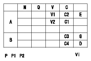
A:Potentiometer standards
B:ON, OFF switch standard
G:ON-->OFF
D:OFF-->ON
E:Adjusting point
F:Checking point
P:Boost pressure
Vi:Applied voltage
C1:Full-speed
C2:Idle
Q:Injection quantity
N:Pump speed
V:Output voltage
C:Control lever angle
----------
----------
V1=1.6+-0.03V V2=7.6+-1.1V C3=(4.9+-2.5)deg C4=(19.4+-4)deg Vi=10V P1=-kPa P2=-mmHg
----------
----------
V1=1.6+-0.03V V2=7.6+-1.1V C3=(4.9+-2.5)deg C4=(19.4+-4)deg Vi=10V P1=-kPa P2=-mmHg
Information:
Remove Timing Gears And Plate
start by:a) remove timing gear coverb) remove fuel injection pump and governor drive 1. Remove four bolts (2), plate (3) and idler gear (1).2. Use tooling (A) to remove camshaft gear (4).
Do not turn the crankshaft with camshaft gear removed. Damage can be caused to pistons and valves or both.
3. Remove bolts (5) that hold timing gear plate (6) to cylinder block.4. Remove timing gear plate (6). 5. Use tooling (B) to remove the bearing from the idler gear.Install Timing Gears And Plate
1. Install a new gasket on timing gear plate. 2. Put timing gear plate (1) in position on cylinder block and install the bolts that hold timing gear plate to cylinder block.4. Heat camshaft gear (2) to a maximum temperature of 600°F (315°C) and install it on the camshaft. 5. Use tooling (A) and install the bearing in the idler gear. Install the bearing to a depth of .06 .02 in. (1.5 0.5 mm) below the rear face of the idler gear.6. Install idler gear, plate and bolts. Be sure No. 1 cylinder is at top center on compression stroke. Install idler gear so the "V" mark (4) on idler gear is in alignment with "V" mark on crankshaft gear. The "K" marks (3) of camshaft gear can be seen at outer edges of idler gear.end by:a) install fuel injection pump and governor driveb) install timing gear cover