Information injection-pump assembly
ZEXEL
104745-9011
1047459011
Rating:
Cross reference number
ZEXEL
104745-9011
1047459011
Zexel num
Bosch num
Firm num
Name
104745-9011
INJECTION-PUMP ASSEMBLY
Calibration Data:
Adjustment conditions
Test oil
1404 Test oil ISO4113orSAEJ967d
1404 Test oil ISO4113orSAEJ967d
Test oil temperature
degC
45
45
50
Nozzle
105780-0060
Bosch type code
NP-DN0SD1510
Nozzle holder
105780-2150
Opening pressure
MPa
13
13
13.3
Opening pressure
kgf/cm2
133
133
136
Injection pipe
157805-7320
Injection pipe
Inside diameter - outside diameter - length (mm) mm 2-6-450
Inside diameter - outside diameter - length (mm) mm 2-6-450
Joint assembly
157641-4720
Tube assembly
157641-4020
Transfer pump pressure
kPa
20
20
20
Transfer pump pressure
kgf/cm2
0.2
0.2
0.2
Direction of rotation (viewed from drive side)
Right R
Right R
Injection timing adjustment
Pump speed
r/min
1100
1100
1100
Average injection quantity
mm3/st.
49.9
49.4
50.4
Difference in delivery
mm3/st.
4
Basic
*
Oil temperature
degC
50
48
52
Injection timing adjustment_02
Pump speed
r/min
500
500
500
Average injection quantity
mm3/st.
41.3
38.8
43.8
Oil temperature
degC
48
46
50
Injection timing adjustment_03
Pump speed
r/min
1100
1100
1100
Average injection quantity
mm3/st.
49.9
48.9
50.9
Difference in delivery
mm3/st.
4.5
Basic
*
Oil temperature
degC
50
48
52
Injection timing adjustment_04
Pump speed
r/min
2150
2150
2150
Average injection quantity
mm3/st.
46.3
43.8
48.8
Oil temperature
degC
52
50
54
Injection quantity adjustment
Pump speed
r/min
2550
2550
2550
Average injection quantity
mm3/st.
10.9
8.9
12.9
Difference in delivery
mm3/st.
3
Basic
*
Oil temperature
degC
55
52
58
Injection quantity adjustment_02
Pump speed
r/min
2700
2700
2700
Average injection quantity
mm3/st.
5
Oil temperature
degC
55
52
58
Injection quantity adjustment_03
Pump speed
r/min
2350
2350
2350
Average injection quantity
mm3/st.
39.7
39.7
39.7
Oil temperature
degC
52
50
54
Injection quantity adjustment_04
Pump speed
r/min
2550
2550
2550
Average injection quantity
mm3/st.
10.9
8.4
13.4
Basic
*
Oil temperature
degC
55
52
58
Governor adjustment
Pump speed
r/min
350
350
350
Average injection quantity
mm3/st.
7.7
5.7
9.7
Difference in delivery
mm3/st.
2
Basic
*
Oil temperature
degC
48
46
50
Governor adjustment_02
Pump speed
r/min
350
350
350
Average injection quantity
mm3/st.
7.7
5.2
10.2
Difference in delivery
mm3/st.
2.5
Basic
*
Oil temperature
degC
48
46
50
Timer adjustment
Pump speed
r/min
100
100
100
Average injection quantity
mm3/st.
60
45
80
Basic
*
Oil temperature
degC
48
46
50
Remarks
Full
Full
Timer adjustment_02
Pump speed
r/min
100
100
100
Average injection quantity
mm3/st.
60
45
80
Oil temperature
degC
48
46
50
Remarks
Full
Full
Speed control lever angle
Pump speed
r/min
350
350
350
Average injection quantity
mm3/st.
0
0
0
Oil temperature
degC
48
46
50
Remarks
Magnet OFF at idling position
Magnet OFF at idling position
0000000901
Pump speed
r/min
1100
1100
1100
Overflow quantity with S/T ON
cm3/min
390
260
520
Oil temperature
degC
50
48
52
Remarks
With an O-ring
With an O-ring
_02
Overflow quantity with S/T ON
cm3/min
600
470
730
Oil temperature
degC
50
48
52
Remarks
Without an O-ring
Without an O-ring
Stop lever angle
Pump speed
r/min
1100
1100
1100
Pressure with S/T ON
kPa
520
481
559
Pressure with S/T ON
kgf/cm2
5.3
4.9
5.7
Pressure with S/T OFF
kPa
431
402
460
Pressure with S/T OFF
kgf/cm2
4.4
4.1
4.7
Basic
*
Oil temperature
degC
50
48
52
Remarks
OFF
OFF
Stop lever angle_02
Pump speed
r/min
1100
1100
1100
Pressure with S/T OFF
kPa
431
392
470
Pressure with S/T OFF
kgf/cm2
4.4
4
4.8
Basic
*
Oil temperature
degC
50
48
52
Stop lever angle_03
Pump speed
r/min
1700
1700
1700
Pressure with S/T OFF
kPa
559
520
598
Pressure with S/T OFF
kgf/cm2
5.7
5.3
6.1
Oil temperature
degC
50
48
52
0000001101
Pump speed
r/min
1100
1100
1100
Timer stroke with S/T ON
mm
3.4
3
3.8
Timer stroke with S/T OFF
mm
1.9
1.7
2.1
Basic
*
Oil temperature
degC
50
48
52
Remarks
OFF
OFF
_02
Pump speed
r/min
850
850
850
Timer stroke with S/T OFF
mm
0.5
0
1
Oil temperature
degC
50
48
52
_03
Pump speed
r/min
1100
1100
1100
Timer stroke with S/T ON
mm
3.4
2.9
3.9
Timer stroke with S/T OFF
mm
1.9
1.6
2.2
Basic
*
Oil temperature
degC
50
48
52
_04
Pump speed
r/min
1700
1700
1700
Timer stroke with S/T OFF
mm
4.4
3.9
4.9
Oil temperature
degC
50
48
52
_05
Pump speed
r/min
2300
2300
2300
Timer stroke with S/T OFF
mm
6.1
5.6
6.5
Oil temperature
degC
52
50
54
0000001201
Max. applied voltage
V
8
8
8
Test voltage
V
13
12
14
0000001401
Pump speed
r/min
1100
1100
1100
Average injection quantity
mm3/st.
31
30.5
31.5
Timer stroke TA
mm
1.2
1
1.4
Timer stroke variation dT
mm
0.7
0.7
0.7
Basic
*
Oil temperature
degC
50
48
52
_02
Pump speed
r/min
1100
1100
1100
Average injection quantity
mm3/st.
31
30
32
Timer stroke TA
mm
1.2
0.9
1.5
Basic
*
Oil temperature
degC
50
48
52
_03
Pump speed
r/min
1100
1100
1100
Average injection quantity
mm3/st.
22
19.5
24.5
Timer stroke TA
mm
0.6
0.1
1.1
Oil temperature
degC
50
48
52
Timing setting
K dimension
mm
3.3
3.2
3.4
KF dimension
mm
5.8
5.7
5.9
MS dimension
mm
0.9
0.8
1
Pre-stroke
mm
0.1
0.08
0.12
Control lever angle alpha
deg.
25
23
27
Control lever angle beta
deg.
36
31
41
Test data Ex:
0000001801 POTENTIOMETER ADJUSTMENT
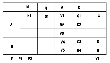
Potentiometer adjustment
1. Applied voltage: Vi
2. Boost pressure = P1kPa {P2 mmHg}
3. Set the control lever at the adjusting point. Position the dummy bolt against the lever and fix.
4. Assemble the potentiometer to obtain output voltage V1 (V) at the fixed position.
5. After mounting the potentiometer, remove the dummy bolt.
At TCV duty 100%
A:Adjusting point
B:Performance standards
C:Control lever angle
N:Pump speed
V:Output voltage
Q:Injection quantity
C1:Idle
C2:Full speed
----------
----------
N1=-r/min Q1=-cm3/1,000st V1=1.6+-0.03V V2=7.6+-1.1V V3=-V V4=-V V5=-V C3=(4.9+-2.5)deg C4=(19.4+-4)deg P1=-kPa P2=-mmHg Vi=10V
----------
----------
N1=-r/min Q1=-cm3/1,000st V1=1.6+-0.03V V2=7.6+-1.1V V3=-V V4=-V V5=-V C3=(4.9+-2.5)deg C4=(19.4+-4)deg P1=-kPa P2=-mmHg Vi=10V
Information:
start by: a) remove vibration damper and pulley 1. Use tooling (A) to remove the crankshaft front seal from the timing gear cover. When a replacement of the front seal is made, a replacement of the wear sleeve is to be made also. 2. Put tool (B) in position in the seal bore as shown.3. Install tool (C) between tool (B) and the wear sleeve. Turn tool (C) until the edge of the tool makes a flat place (crease) in the wear sleeve. Do this in two or more places until the wear sleeve is loose.4. Remove tool (B) and the wear sleeve by hand.5. Clean and make a preparation of the wear sleeve inside diameter and crankshaft outside diameter with 8M8060 Quick Cure Primer. Put 9S3265 Retaining Compound on the crankshaft outside diameter and wear sleeve inside diameter before the wear sleeve is installed on the crankshaft. 6. Put a small amount of clean oil on the lip of the seal. Install wear sleeve (2) and seal (1) on the crankshaft as shown with tools (D). If tools are not available, install the wear sleeve until it is .060 .020 in. (1.52 0.51 mm) (dimension "X") from the face of the crankshaft. Install the seal in the timing gear cover until the metal face of the seal is .090 .020 in. (2.29 0.51 mm) (dimension "Y") from the face of the crankshaft.end by: a) install vibration damper and pulleyRemove And Install Crankshaft Rear Seal And Wear Sleeve
start by:a) remove flywheel 1. Use tool (A) to remove crankshaft rear seal (1) from the flywheel housing. When a replacement of the rear seal is made, a replacement of the wear sleeve is to be made also.
TYPICAL EXAMPLE2. Put tool (B) in position in the seal bore as shown.3. Install tool (C) between tool (B) and the wear sleeve. Turn tool (C) until the edge of the tool makes a flat place (crease) in the wear sleeve. Do this in two or more places until the wear sleeve is loose.4. Remove tool (B) and the wear sleeve by hand.5. Clean and make a preparation of the wear sleeve inside diameter and adapter outside diameter with 8M8060 Quick Cure Primer. Put 9S3265 Retaining Compound on the adapter outside diameter and wear sleeve inside diameter before the wear sleeve is installed on the adapter. Make sure the lip of the seal is toward the inside of the engine and the outside diameter bevel of the wear sleeve is toward the outside of the engine.6. Put a small amount of clean engine oil on the lip of the seal. Install the wear sleeve and the seal on the crankshaft as shown with tools (D).end by:a) install flywheel
Have questions with 104745-9011?
Group cross 104745-9011 ZEXEL
Nissan-Diesel
104745-9011
INJECTION-PUMP ASSEMBLY