Information injection-pump assembly
ZEXEL
104745-9010
1047459010
NISSAN-DIESEL
167006T003
167006t003
Rating:
Cross reference number
ZEXEL
104745-9010
1047459010
NISSAN-DIESEL
167006T003
167006t003
Zexel num
Bosch num
Firm num
Name
Calibration Data:
Adjustment conditions
Test oil
1404 Test oil ISO4113orSAEJ967d
1404 Test oil ISO4113orSAEJ967d
Test oil temperature
degC
45
45
50
Nozzle
105780-0060
Bosch type code
NP-DN0SD1510
Nozzle holder
105780-2150
Opening pressure
MPa
13
13
13.3
Opening pressure
kgf/cm2
133
133
136
Injection pipe
157805-7320
Injection pipe
Inside diameter - outside diameter - length (mm) mm 2-6-450
Inside diameter - outside diameter - length (mm) mm 2-6-450
Joint assembly
157641-4720
Tube assembly
157641-4020
Transfer pump pressure
kPa
20
20
20
Transfer pump pressure
kgf/cm2
0.2
0.2
0.2
Direction of rotation (viewed from drive side)
Right R
Right R
Injection timing adjustment
Pump speed
r/min
1100
1100
1100
Average injection quantity
mm3/st.
45.3
44.8
45.8
Difference in delivery
mm3/st.
3
Basic
*
Oil temperature
degC
50
48
52
Injection timing adjustment_02
Pump speed
r/min
500
500
500
Average injection quantity
mm3/st.
43
40.5
45.5
Oil temperature
degC
48
46
50
Injection timing adjustment_03
Pump speed
r/min
1100
1100
1100
Average injection quantity
mm3/st.
45.3
44.3
46.3
Difference in delivery
mm3/st.
3.5
Basic
*
Oil temperature
degC
50
48
52
Injection timing adjustment_04
Pump speed
r/min
2150
2150
2150
Average injection quantity
mm3/st.
43
40.5
45.5
Oil temperature
degC
52
50
54
Injection quantity adjustment
Pump speed
r/min
2350
2350
2350
Average injection quantity
mm3/st.
38
36
40
Basic
*
Oil temperature
degC
52
50
54
Injection quantity adjustment_02
Pump speed
r/min
2700
2700
2700
Average injection quantity
mm3/st.
5
Oil temperature
degC
55
52
58
Injection quantity adjustment_03
Pump speed
r/min
2350
2350
2350
Average injection quantity
mm3/st.
38
35.5
40.5
Oil temperature
degC
52
50
54
Injection quantity adjustment_04
Pump speed
r/min
2550
2550
2550
Average injection quantity
mm3/st.
11.5
7
16
Basic
*
Oil temperature
degC
55
52
58
Governor adjustment
Pump speed
r/min
350
350
350
Average injection quantity
mm3/st.
7.4
5.4
9.4
Difference in delivery
mm3/st.
2
Basic
*
Oil temperature
degC
48
46
50
Governor adjustment_02
Pump speed
r/min
350
350
350
Average injection quantity
mm3/st.
7.4
4.9
9.9
Difference in delivery
mm3/st.
2.5
Basic
*
Oil temperature
degC
48
46
50
Timer adjustment
Pump speed
r/min
100
100
100
Average injection quantity
mm3/st.
60
50
80
Basic
*
Oil temperature
degC
48
46
50
Remarks
Full
Full
Timer adjustment_02
Pump speed
r/min
100
100
100
Average injection quantity
mm3/st.
60
45
80
Oil temperature
degC
48
46
50
Remarks
Full
Full
Speed control lever angle
Pump speed
r/min
350
350
350
Average injection quantity
mm3/st.
0
0
0
Oil temperature
degC
48
46
50
Remarks
Magnet OFF at idling position
Magnet OFF at idling position
0000000901
Pump speed
r/min
1100
1100
1100
Overflow quantity with S/T ON
cm3/min
390
260
520
Oil temperature
degC
50
48
52
Remarks
With an O-ring
With an O-ring
_02
Pump speed
r/min
1000
1000
1000
Overflow quantity with S/T ON
cm3/min
470
340
600
Oil temperature
degC
50
48
52
Remarks
Without an O-ring
Without an O-ring
Stop lever angle
Pump speed
r/min
1100
1100
1100
Pressure with S/T ON
kPa
539
500
578
Pressure with S/T ON
kgf/cm2
5.5
5.1
5.9
Pressure with S/T OFF
kPa
431
402
460
Pressure with S/T OFF
kgf/cm2
4.4
4.1
4.7
Basic
*
Oil temperature
degC
50
48
52
Remarks
OFF
OFF
Stop lever angle_02
Pump speed
r/min
1100
1100
1100
Pressure with S/T OFF
kPa
431
392
470
Pressure with S/T OFF
kgf/cm2
4.4
4
4.8
Basic
*
Oil temperature
degC
50
48
52
Stop lever angle_03
Pump speed
r/min
1700
1700
1700
Pressure with S/T OFF
kPa
579
540
618
Pressure with S/T OFF
kgf/cm2
5.9
5.5
6.3
Oil temperature
degC
50
48
52
0000001101
Pump speed
r/min
1100
1100
1100
Timer stroke with S/T ON
mm
4.3
3.9
4.7
Timer stroke with S/T OFF
mm
2.6
2.4
2.8
Basic
*
Oil temperature
degC
50
48
52
Remarks
OFF
OFF
_02
Pump speed
r/min
700
700
700
Timer stroke with S/T OFF
mm
0.5
0.5
Oil temperature
degC
50
48
52
_03
Pump speed
r/min
1100
1100
1100
Timer stroke with S/T ON
mm
4.3
3.8
4.8
Timer stroke with S/T OFF
mm
2.6
2.3
2.9
Basic
*
Oil temperature
degC
50
48
52
_04
Pump speed
r/min
1700
1700
1700
Timer stroke with S/T OFF
mm
4.9
4.4
5.4
Oil temperature
degC
50
48
52
_05
Pump speed
r/min
2550
2550
2550
Timer stroke with S/T OFF
mm
7.4
6.9
7.8
Oil temperature
degC
55
52
58
0000001201
Max. applied voltage
V
8
8
8
Test voltage
V
13
12
14
Timing setting
K dimension
mm
3.3
3.2
3.4
KF dimension
mm
5.8
5.7
5.9
MS dimension
mm
0.9
0.8
1
Pre-stroke
mm
0.1
0.08
0.12
Control lever angle alpha
deg.
25
23
27
Control lever angle beta
deg.
36
31
41
Test data Ex:
0000001801 POTENTIOMETER ADJUSTMENT
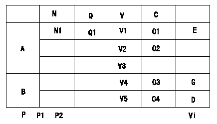
Potentiometer adjustment
1. Applied voltage: Vi
2. Boost pressure = P1kPa {P2 mmHg}
3. Set the control lever at the adjusting point. Position the dummy bolt against the lever and fix.
4. Assemble the potentiometer to obtain output voltage V1 (V) at the fixed position.
5. After mounting the potentiometer, remove the dummy bolt.
At TCV duty 100%
A:Adjusting point
B:Performance standards
C:Control lever angle
N:Pump speed
V:Output voltage
Q:Injection quantity
C1:Idle
C2:Full speed
----------
----------
N1=-r/min Q1=-cm3/1,000st V1=1.6+-0.03V V2=7.6+-1.1V V3=-V V4=-V V5=-V C3=4.9+-2.5deg C4=19.4+-4deg P1=-kPa P2=-mmHg Vi=10V
----------
----------
N1=-r/min Q1=-cm3/1,000st V1=1.6+-0.03V V2=7.6+-1.1V V3=-V V4=-V V5=-V C3=4.9+-2.5deg C4=19.4+-4deg P1=-kPa P2=-mmHg Vi=10V
Information:
start by:a) remove pistons1. Put covers on journals of crankshaft for protection from dirt or water. 2. Remove the cylinder liners with tool (A) as shown.Install Cylinder Liners
1. Clean the cylinder liners and the liner bores in the cylinder block. 2. Install cylinder liners (1) in the block without the O-ring seals or filler band.3. Check the cylinder liner projection as follows: a) Install the 3/4"-16 NF bolts, 3 in. long and the 2F126 Washers of tooling (A) on the cylinder block next to each liner. Tighten the bolts evenly, in four steps: 10 lb.ft. (14 N m), 25 lb.ft. (35 N m) 50 lb.ft. (70 N m) and then turn to 70 lb.ft. (95 N m).b) Put the adapter plate and one plate of tooling (A) on top of the liner and install the remainder of tooling (A). Be sure the bar is in position at the center of the liner. Tighten the bolts evenly, in four steps to a torque of: 5 lb.ft. (7 N m), 15 lb.ft. (20 N m), 25 lb.ft. (35 N m), then to 50 lb.ft. (70 N m).c) Check to be sure the distance from the bottom edge of the bar to the top of the cylinder block is the same on both sides of the liner. d) Check the cylinder liner projection with tooling (B) at four locations around the liner. SPECIAL INSTRUCTION (GMG00623) is included with the tool.e) Liner projection must be .001 to .006 in. (0.03 to 0.15 mm). Measurements on the same liner must not be different by more than .002 in. (0.05 mm). Average measurements between liners next to each other must not be different by more than .002 in. (0.05 mm).The maximum difference in the average projection for all cylinder liners under one cylinder head must ot be more than .004 in. (0.10 mm). If the liner is turned in the bore it can make a difference in the liner projection.f. If the liner projection is not .001 to .006 in. (0.03 to 0.15 mm), check the thickness of the following parts: spacer plate, spacer plate gasket, and cylinder liner flange (3). The thickness of the spacer plate must be .338 .001 in. (8.59 0.03 mm). The thickness of the spacer plate gasket must be .008 .001 in. (0.20 0.03 mm). The thickness of the cylinder liner flange must be .3500 .0008 in. (8.890 0.020 mm). The cylinder liner projection can be changed by the correction of the counterbore in the block to a minimum depth of .030 in. (0.76 mm) with a cylinder block counterboring tool. See SPECIAL INSTRUCTION, Form FM055228. Shims are available for the adjustment of the liner projection. 5. Put a mark on the liner and block so the liner can be installed in the same position from which it was removed.6. Remove tooling (a) and (B). Remove the liner. Install new O-ring seals on the liners. 7. Put liquid soap on the O-ring seals
1. Clean the cylinder liners and the liner bores in the cylinder block. 2. Install cylinder liners (1) in the block without the O-ring seals or filler band.3. Check the cylinder liner projection as follows: a) Install the 3/4"-16 NF bolts, 3 in. long and the 2F126 Washers of tooling (A) on the cylinder block next to each liner. Tighten the bolts evenly, in four steps: 10 lb.ft. (14 N m), 25 lb.ft. (35 N m) 50 lb.ft. (70 N m) and then turn to 70 lb.ft. (95 N m).b) Put the adapter plate and one plate of tooling (A) on top of the liner and install the remainder of tooling (A). Be sure the bar is in position at the center of the liner. Tighten the bolts evenly, in four steps to a torque of: 5 lb.ft. (7 N m), 15 lb.ft. (20 N m), 25 lb.ft. (35 N m), then to 50 lb.ft. (70 N m).c) Check to be sure the distance from the bottom edge of the bar to the top of the cylinder block is the same on both sides of the liner. d) Check the cylinder liner projection with tooling (B) at four locations around the liner. SPECIAL INSTRUCTION (GMG00623) is included with the tool.e) Liner projection must be .001 to .006 in. (0.03 to 0.15 mm). Measurements on the same liner must not be different by more than .002 in. (0.05 mm). Average measurements between liners next to each other must not be different by more than .002 in. (0.05 mm).The maximum difference in the average projection for all cylinder liners under one cylinder head must ot be more than .004 in. (0.10 mm). If the liner is turned in the bore it can make a difference in the liner projection.f. If the liner projection is not .001 to .006 in. (0.03 to 0.15 mm), check the thickness of the following parts: spacer plate, spacer plate gasket, and cylinder liner flange (3). The thickness of the spacer plate must be .338 .001 in. (8.59 0.03 mm). The thickness of the spacer plate gasket must be .008 .001 in. (0.20 0.03 mm). The thickness of the cylinder liner flange must be .3500 .0008 in. (8.890 0.020 mm). The cylinder liner projection can be changed by the correction of the counterbore in the block to a minimum depth of .030 in. (0.76 mm) with a cylinder block counterboring tool. See SPECIAL INSTRUCTION, Form FM055228. Shims are available for the adjustment of the liner projection. 5. Put a mark on the liner and block so the liner can be installed in the same position from which it was removed.6. Remove tooling (a) and (B). Remove the liner. Install new O-ring seals on the liners. 7. Put liquid soap on the O-ring seals