Information injection-pump assembly
BOSCH
9 460 611 962
9460611962
ZEXEL
104745-9003
1047459003
NISSAN
167006T016
167006t016
Rating:
Components :
| 0. | INJECTION-PUMP ASSEMBLY | 104745-9003 |
| 1. | _ | |
| 2. | FUEL INJECTION PUMP | 104645-9002 |
| 3. | NUMBER PLATE | 146959-5900 |
| 4. | _ | |
| 5. | CAPSULE | |
| 6. | ADJUSTING DEVICE | |
| 7. | NOZZLE AND HOLDER ASSY | 105148-1221 |
| 8. | Nozzle and Holder | 16600-63G01 |
| 9. | Open Pre:MPa(Kqf/cm2) | 9.8{100} |
| 10. | NOZZLE-HOLDER | 105078-0050 |
| 11. | NOZZLE | 105007-1210 |
Scheme ###:
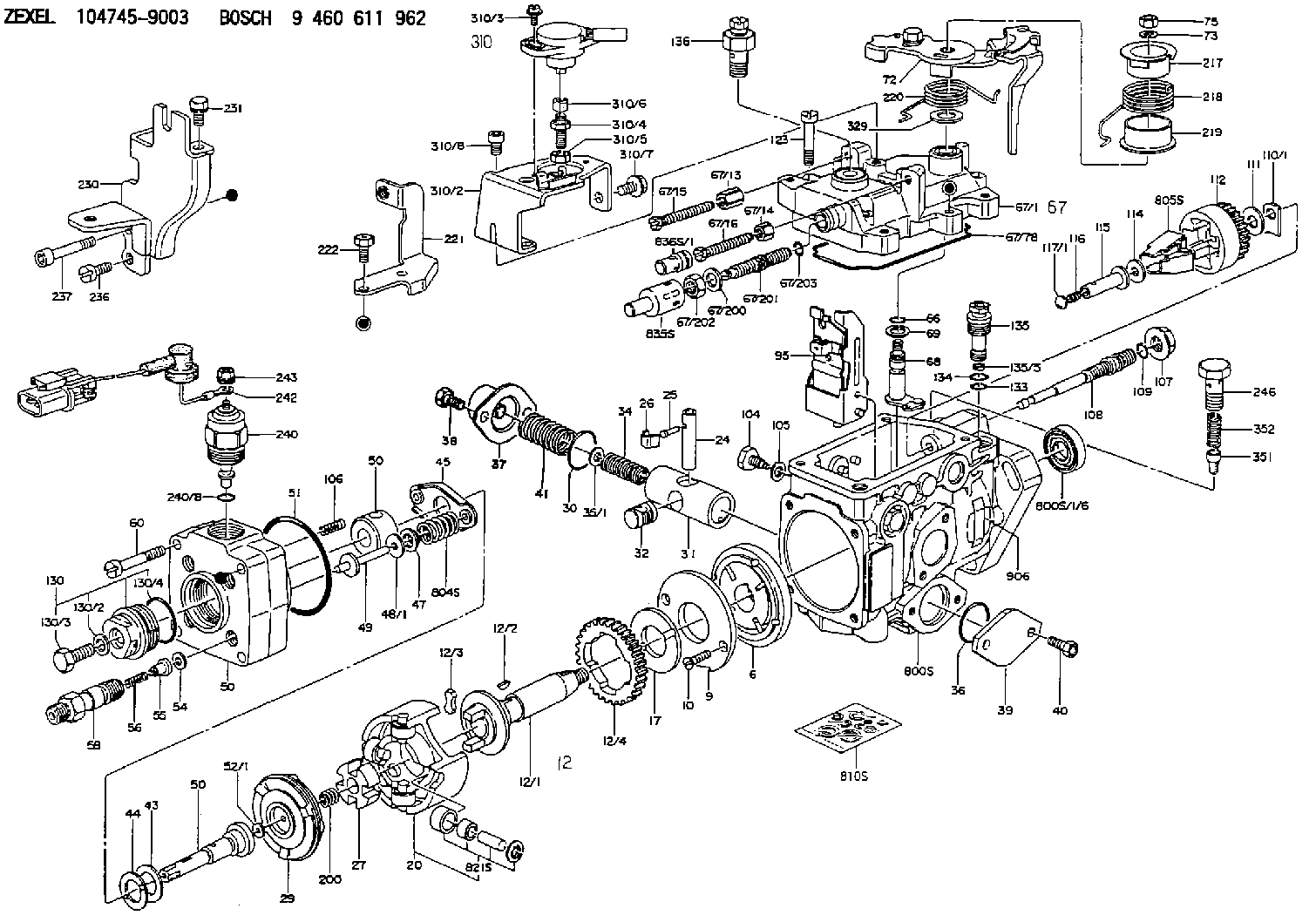
| 1/6. | [1] | 146601-0900 | PACKING RING |
| 6. | [1] | 146100-0420 | SUPPLY PUMP |
| 9. | [1] | 146103-0100 | COVER |
| 10. | [2] | 139104-0000 | FLAT-HEAD SCREW |
| 12. | [1] | 146200-0020 | DRIVE SHAFT |
| 12/1. | [1] | 146200-0000 | DRIVE SHAFT |
| 12/2. | [1] | 146201-0000 | WOODRUFF KEY |
| 12/3. | [2] | 146202-0100 | DAMPER |
| 12/4. | [1] | 146203-0000 | TOOTHED GEAR |
| 17. | [1] | 146204-0000 | PLAIN WASHER |
| 20. | [1] | 146210-2320 | ROLLER SET |
| 24. | [1] | 146303-0000 | BEARING PIN |
| 25. | [1] | 146304-0000 | BEARING PIN |
| 26. | [1] | 146305-0000 | CLAMPING BAND |
| 27. | [1] | 146205-0000 | SLOTTED WASHER |
| 29. | [1] | 146220-2120 | CAM PLATE |
| 30. | [1] | 146600-0800 | O-RING |
| 31. | [1] | 146311-5920 | PUMP PLUNGER |
| 32. | [1] | 146301-0000 | SLIDING PIECE |
| 34. | [1] | 146312-2900 | COMPRESSION SPRING |
| 34B. | [1] | 146312-3000 | COMPRESSION SPRING |
| 34C. | [1] | 146312-2800 | COMPRESSION SPRING |
| 35/1. | [1] | 146690-3200 | SHIM D11.5&9.4T0.1 |
| 35/1. | [1] | 146690-3300 | SHIM D11.5&9.4T0.2 |
| 35/1. | [1] | 146690-3400 | SHIM D11.5&9.4T0.25 |
| 35/1. | [1] | 146690-3500 | SHIM D11.5&9.4T1.0 |
| 35/1. | [1] | 146690-4100 | SHIM D11.5&9.4T2 |
| 35/1. | [1] | 146690-4200 | SHIM D11.5&9.4T0.5 |
| 35/1. | [1] | 146690-4300 | SHIM D11.5&9.4T0.75 |
| 36. | [1] | 146600-0800 | O-RING |
| 37. | [1] | 146310-4020 | COVER |
| 38. | [2] | 146620-5000 | BLEEDER SCREW |
| 39. | [1] | 146310-0100 | COVER |
| 40. | [2] | 146620-5000 | BLEEDER SCREW |
| 41. | [1] | 146312-1900 | COMPRESSION SPRING |
| 43. | [1] | 146230-0000 | SHIM |
| 44. | [1] | 146230-0100 | PLAIN WASHER |
| 45. | [1] | 146231-0001 | SLOTTED WASHER |
| 47. | [2] | 146233-0000 | SLOTTED WASHER |
| 48/1. | [1] | 146603-0100 | SHIM D17.0&5.2T0.80 |
| 48/1. | [1] | 146603-0200 | SHIM D17.0&5.2T1.00 |
| 48/1. | [1] | 146603-0300 | SHIM D17.0&5.2T1.20 |
| 48/1. | [1] | 146603-0400 | SHIM D17.0&5.2T1.50 |
| 48/1. | [1] | 146690-1400 | SHIM D17&5.2T0.9 |
| 48/1. | [1] | 146690-1500 | SHIM D17&5.2T1.1 |
| 48/1. | [1] | 146690-1600 | SHIM D17&5.2T1.3 |
| 48/1. | [1] | 146690-1700 | SHIM D17&5.2T1.4 |
| 48/1. | [1] | 146690-1800 | SHIM D17&5.2T1.6 |
| 49. | [2] | 146234-0500 | GUIDE PIN |
| 50. | [1] | 146401-3720 | HYDRAULIC HEAD |
| 50. | [1] | 146401-3720 | HYDRAULIC HEAD |
| 50. | [1] | 146401-3720 | HYDRAULIC HEAD |
| 51. | [1] | 146600-0000 | O-RING |
| 52/1. | [1] | 146420-0700 | SHIM D9.5&3.0T2.04 |
| 52/1. | [1] | 146420-0800 | SHIM D9.5&3.0T2.06 |
| 52/1. | [1] | 146420-0900 | SHIM D9.5&3.0T2.08 |
| 52/1. | [1] | 146420-1000 | SHIM D9.5&3.0T2.10 |
| 52/1. | [1] | 146420-1100 | SHIM D9.5&3.0T2.12 |
| 52/1. | [1] | 146420-1200 | SHIM D9.5&3.0T2.14 |
| 52/1. | [1] | 146420-1300 | SHIM D9.5&3.0T2.16 |
| 52/1. | [1] | 146420-1400 | SHIM D9.5&3.0T2.18 |
| 52/1. | [1] | 146420-1500 | SHIM D9.5&3.0T2.20 |
| 52/1. | [1] | 146420-1600 | SHIM D9.5&3.0T2.22 |
| 52/1. | [1] | 146420-1700 | SHIM D9.5&3.0T2.24 |
| 52/1. | [1] | 146420-1800 | SHIM D9.5&3.0T2.26 |
| 52/1. | [1] | 146420-1900 | SHIM D9.5&3.0T2.28 |
| 52/1. | [1] | 146420-2000 | SHIM D9.5&3.0T2.30 |
| 52/1. | [1] | 146420-2100 | SHIM D9.5&3.0T2.32 |
| 52/1. | [1] | 146420-2200 | SHIM D9.5&3.0T2.34 |
| 52/1. | [1] | 146420-2400 | SHIM D9.5&3.0T2.38 |
| 52/1. | [1] | 146420-2500 | SHIM D9.5&3.0T2.40 |
| 52/1. | [1] | 146420-2600 | SHIM D9.5&3.0T2.42 |
| 52/1. | [1] | 146420-2700 | SHIM D9.5&3.0T2.44 |
| 52/1. | [1] | 146420-2800 | SHIM D9.5&3.0T2.46 |
| 52/1. | [1] | 146420-2900 | SHIM D9.5&3.0T2.48 |
| 52/1. | [1] | 146420-3000 | SHIM D9.5&3.0T2.50 |
| 52/1. | [1] | 146420-3100 | SHIM D9.5&3.0T2.52 |
| 52/1. | [1] | 146420-3200 | SHIM D9.5&3.0T2.54 |
| 52/1. | [1] | 146420-3300 | SHIM D9.5&3.0T2.56 |
| 52/1. | [1] | 146420-3400 | SHIM D9.5&3.0T2.58 |
| 52/1. | [1] | 146420-3500 | SHIM D9.5&3.0T2.60 |
| 52/1. | [1] | 146420-3600 | SHIM D9.5&3.0T2.62 |
| 52/1. | [1] | 146420-3700 | SHIM D9.5&3.0T2.64 |
| 52/1. | [1] | 146420-3800 | SHIM D9.5&3.0T2.66 |
| 52/1. | [1] | 146420-3900 | SHIM D9.5&3.0T2.68 |
| 52/1. | [1] | 146420-4000 | SHIM D9.5&3.0T2.70 |
| 52/1. | [1] | 146420-4100 | SHIM D9.5&3.0T2.72 |
| 54. | [4] | 146433-0100 | GASKET |
| 55. | [4] | 146430-0320 | DELIVERY-VALVE ASSEMBLY VE4 |
| 56. | [4] | 146432-0000 | COMPRESSION SPRING |
| 58. | [4] | 146440-0220 | FITTING |
| 60. | [3] | 139106-0100 | FLAT-HEAD SCREW |
| 66. | [1] | 146600-0100 | O-RING |
| 67. | [1] | 146503-2220 | GOVERNOR COVER |
| 67/1. | [1] | 146508-2221 | GOVERNOR COVER |
| 67/13. | [1] | 146621-3100 | UNION NUT |
| 67/14. | [1] | 146621-1700 | UNION NUT |
| 67/15. | [1] | 146526-6400 | BLEEDER SCREW |
| 67/16. | [1] | 146526-3400 | BLEEDER SCREW |
| 67/78. | [1] | 146600-4400 | SEAL RING |
| 67/200. | [1] | 139308-0300 | PLAIN WASHER |
| 67/201. | [1] | 146545-3400 | THREADED PIN L53.00 |
| 67/201B. | [1] | 146545-3500 | THREADED PIN L55.00 |
| 67/201C. | [1] | 146545-3600 | THREADED PIN L57.00 |
| 67/202. | [1] | 139208-0900 | UNION NUT |
| 67/203. | [1] | 146600-1200 | O-RING |
| 68. | [1] | 146810-2620 | CONTROL SHAFT |
| 69. | [1] | 139310-0200 | PLAIN WASHER |
| 72. | [1] | 146537-7320 | CONTROL LEVER |
| 73. | [1] | 014110-6440 | LOCKING WASHER D12.2&6.1T1.5 |
| 75. | [1] | 146621-0700 | UNION NUT |
| 95. | [1] | 146861-4820 | FULCRUM LEVER |
| 104. | [2] | 146568-0000 | SLOTTED SPRING PIN |
| 105. | [2] | 026508-1140 | GASKET D11.4&8.2T1.0 |
| 106. | [2] | 146588-0500 | COILED SPRING |
| 107. | [1] | 146569-0300 | UNION NUT |
| 108. | [1] | 146570-0420 | GOVERNOR SHAFT |
| 109. | [1] | 146600-0400 | O-RING |
| 110/1. | [1] | 146571-0000 | SHIM D20.2&8.3T1.05 |
| 110/1. | [1] | 146571-0100 | SHIM D20.2&8.3T1.25 |
| 110/1. | [1] | 146571-0200 | SHIM D20.2&8.3T1.45 |
| 110/1. | [1] | 146571-0300 | SHIM D20.2&8.3T1.65 |
| 110/1. | [1] | 146571-0400 | SHIM D20.2&8.3T1.85 |
| 111. | [1] | 146602-0600 | PLAIN WASHER |
| 112. | [1] | 146572-0020 | FLYWEIGHT ASSEMBLY |
| 114. | [1] | 146602-0500 | PLAIN WASHER |
| 115. | [1] | 146975-6600 | SLIDING SLEEVE |
| 116. | [1] | 146576-0200 | CAP |
| 117/1. | [1] | 146577-2400 | PLUG L3.30 |
| 117/1. | [1] | 146577-2500 | PLUG L3.50 |
| 117/1. | [1] | 146577-2600 | PLUG L3.70 |
| 117/1. | [1] | 146577-2700 | PLUG L3.90 |
| 117/1. | [1] | 146577-2800 | PLUG L4.10 |
| 117/1. | [1] | 146577-2900 | PLUG L4.30 |
| 117/1. | [1] | 146577-3000 | PLUG L4.50 |
| 117/1. | [1] | 146577-3100 | PLUG L4.70 |
| 117/1. | [1] | 146577-7200 | PLUG L3.2 |
| 117/1. | [1] | 146577-7300 | PLUG L3.4 |
| 117/1. | [1] | 146577-7400 | PLUG L3.6 |
| 117/1. | [1] | 146577-7500 | PLUG L3.8 |
| 117/1. | [1] | 146577-7600 | PLUG L4.0 |
| 117/1. | [1] | 146577-7700 | PLUG L4.2 |
| 117/1. | [1] | 146577-7800 | PLUG L4.4 |
| 117/1. | [1] | 146577-7900 | PLUG L4.6 |
| 117/1. | [1] | 146577-8000 | PLUG L4.8 |
| 123. | [4] | 139106-0200 | FLAT-HEAD SCREW |
| 130. | [1] | 146421-0020 | CAPSULE |
| 130/2. | [1] | 026508-1140 | GASKET D11.4&8.2T1.0 |
| 130/3. | [1] | 146422-0000 | BLEEDER SCREW |
| 130/4. | [1] | 146600-0500 | O-RING |
| 133. | [1] | 146600-0600 | O-RING |
| 134. | [1] | 146600-0700 | O-RING |
| 135. | [1] | 146110-0220 | CONTROL VALVE STAMP 02 |
| 135/5. | [1] | 146114-0000 | SPRING WASHER |
| 136. | [1] | 146120-0020 | OVER FLOW VALVE |
| 200. | [1] | 146206-0100 | COILED SPRING |
| 217. | [1] | 146541-3100 | SLOTTED WASHER |
| 218. | [1] | 146587-9900 | COILED SPRING |
| 219. | [1] | 146541-3000 | BUSHING |
| 220. | [1] | 146587-8000 | COILED SPRING |
| 221. | [1] | 146926-9100 | BRACKET |
| 222. | [2] | 139006-4600 | BLEEDER SCREW |
| 230. | [1] | 146926-8220 | BRACKET |
| 231. | [1] | 139006-4600 | BLEEDER SCREW |
| 236. | [1] | 139006-4800 | BLEEDER SCREW |
| 237. | [1] | 146620-0200 | HEX-SOCKET-HEAD CAP SCREW |
| 240. | [1] | 146650-0720 | PULLING ELECTROMAGNET |
| 240/8. | [1] | 146600-1700 | O-RING |
| 242. | [1] | 146658-6720 | WIRE |
| 243. | [0] | 146621-1000 | |
| 243. | [1] | 146621-4901 | UNION NUT |
| 246. | [1] | 027412-2440 | EYE BOLT |
| 310. | [1] | 146673-8421 | POTENTCIOMETER |
| 310/2. | [1] | 146925-8220 | BRACKET |
| 310/3. | [2] | 139104-0400 | FLAT-HEAD SCREW |
| 310/4. | [1] | 146620-2900 | FLAT-HEAD SCREW |
| 310/5. | [1] | 146621-0500 | UNION NUT |
| 310/6. | [1] | 146614-2300 | JOINT CONNECTION |
| 310/7. | [1] | 139006-5700 | BLEEDER SCREW |
| 310/8. | [2] | 010206-1040 | HEX-SOCKET-HEAD CAP SCREW |
| 329. | [1] | 146541-4900 | PLAIN WASHER |
| 351. | [1] | 146125-0101 | FILTER |
| 352. | [1] | 146125-0200 | COILED SPRING |
| 800S. | [1] | 146019-9920 | PUMP HOUSING |
| 800S/1/6. | [1] | 146601-0900 | PACKING RING |
| 800S/1/6. | [1] | 146601-0900 | PACKING RING |
| 804S. | [1] | 146232-0320 | COMPRESSION SPRING |
| 805S. | [1] | 146574-0120 | PARTS SET |
| 810S. | [1] | 146600-1120 | REPAIR SET |
| 821S. | [1] | 146210-5720 | ROLLER SET |
| 835S. | [1] | 146598-1000 | CAP |
| 836S/1. | [1] | 146598-0600 | CAP L18 |
| 836S/1. | [1] | 146598-0700 | CAP L21 |
| 836S/1. | [1] | 146598-0800 | CAP L24 |
| 836S/1. | [1] | 146598-0900 | CAP L27 |
| 906. | [1] | 146959-5900 | NAMEPLATE |
Include in #2:
104745-9003
as INJECTION-PUMP ASSEMBLY
Cross reference number
BOSCH
9 460 611 962
9460611962
ZEXEL
104745-9003
1047459003
NISSAN
167006T016
167006t016
Zexel num
Bosch num
Firm num
Name
104745-9003
9 460 611 962
167006T016 NISSAN
INJECTION-PUMP ASSEMBLY
TD27 K 11CJ INJECTION PUMP ASSY VE4 VE
TD27 K 11CJ INJECTION PUMP ASSY VE4 VE
104745-9003
9 460 611 962
167006T016 NISSAN-DIESEL
INJECTION-PUMP ASSEMBLY
TD27 K 11CJ INJECTION PUMP ASSY VE4 VE
TD27 K 11CJ INJECTION PUMP ASSY VE4 VE
Calibration Data:
Adjustment conditions
Test oil
1404 Test oil ISO4113orSAEJ967d
1404 Test oil ISO4113orSAEJ967d
Test oil temperature
degC
45
45
50
Nozzle
105780-0060
Bosch type code
NP-DN0SD1510
Nozzle holder
105780-2150
Opening pressure
MPa
13
13
13.3
Opening pressure
kgf/cm2
133
133
136
Injection pipe
157805-7320
Injection pipe
Inside diameter - outside diameter - length (mm) mm 2-6-450
Inside diameter - outside diameter - length (mm) mm 2-6-450
Joint assembly
157641-4720
Tube assembly
157641-4020
Transfer pump pressure
kPa
20
20
20
Transfer pump pressure
kgf/cm2
0.2
0.2
0.2
Direction of rotation (viewed from drive side)
Right R
Right R
Injection timing adjustment
Pump speed
r/min
1100
1100
1100
Average injection quantity
mm3/st.
49.9
49.4
50.4
Difference in delivery
mm3/st.
4
Basic
*
Oil temperature
degC
50
48
52
Injection timing adjustment_02
Pump speed
r/min
500
500
500
Average injection quantity
mm3/st.
41.3
38.8
43.8
Oil temperature
degC
48
46
50
Injection timing adjustment_03
Pump speed
r/min
1100
1100
1100
Average injection quantity
mm3/st.
49.9
48.9
50.9
Difference in delivery
mm3/st.
4.5
4.5
4.5
Basic
*
Oil temperature
degC
50
48
52
Injection timing adjustment_04
Pump speed
r/min
2150
2150
2150
Average injection quantity
mm3/st.
46.3
43.8
48.8
Oil temperature
degC
52
50
54
Injection quantity adjustment
Pump speed
r/min
2550
2550
2550
Average injection quantity
mm3/st.
10.9
8.9
12.9
Basic
*
Oil temperature
degC
55
52
58
Injection quantity adjustment_02
Pump speed
r/min
2700
2700
2700
Average injection quantity
mm3/st.
5
Oil temperature
degC
55
52
58
Injection quantity adjustment_03
Pump speed
r/min
2350
2350
2350
Average injection quantity
mm3/st.
39.7
39.7
39.7
Oil temperature
degC
52
50
54
Injection quantity adjustment_04
Pump speed
r/min
2550
2550
2550
Average injection quantity
mm3/st.
10.9
8.4
13.4
Basic
*
Oil temperature
degC
55
52
58
Governor adjustment
Pump speed
r/min
350
350
350
Average injection quantity
mm3/st.
7.7
5.7
9.7
Difference in delivery
mm3/st.
2
Basic
*
Oil temperature
degC
48
46
50
Governor adjustment_02
Pump speed
r/min
350
350
350
Average injection quantity
mm3/st.
7.7
5.2
10.2
Difference in delivery
mm3/st.
2.5
Basic
*
Oil temperature
degC
48
46
50
Timer adjustment
Pump speed
r/min
100
100
100
Average injection quantity
mm3/st.
60
45
80
Basic
*
Oil temperature
degC
48
46
50
Timer adjustment_02
Pump speed
r/min
100
100
100
Average injection quantity
mm3/st.
60
45
80
Oil temperature
degC
48
46
50
Speed control lever angle
Pump speed
r/min
350
350
350
Average injection quantity
mm3/st.
0
0
0
Oil temperature
degC
48
46
50
Remarks
Magnet OFF at idling position
Magnet OFF at idling position
0000000901
Pump speed
r/min
1100
1100
1100
Overflow quantity
cm3/min
390
260
520
Oil temperature
degC
50
48
52
Stop lever angle
Pump speed
r/min
1300
1300
1300
Pressure
kPa
471
442
500
Pressure
kgf/cm2
4.8
4.5
5.1
Basic
*
Oil temperature
degC
50
48
52
Stop lever angle_02
Pump speed
r/min
1300
1300
1300
Pressure
kPa
471
432
510
Pressure
kgf/cm2
4.8
4.4
5.2
Basic
*
Oil temperature
degC
50
48
52
Stop lever angle_03
Pump speed
r/min
2150
2150
2150
Pressure
kPa
647
608
686
Pressure
kgf/cm2
6.6
6.2
7
Oil temperature
degC
52
50
54
0000001101
Pump speed
r/min
1300
1300
1300
Timer stroke
mm
2.1
1.9
2.3
Basic
*
Oil temperature
degC
50
48
52
_02
Pump speed
r/min
1100
1100
1100
Timer stroke
mm
1.1
0.6
1.6
Oil temperature
degC
50
48
52
_03
Pump speed
r/min
1300
1300
1300
Timer stroke
mm
2.1
1.8
2.4
Basic
*
Oil temperature
degC
50
48
52
_04
Pump speed
r/min
2150
2150
2150
Timer stroke
mm
5.6
5
6.2
Oil temperature
degC
52
50
54
_05
Pump speed
r/min
2500
2500
2500
Timer stroke
mm
6.1
5.6
6.5
Oil temperature
degC
55
52
58
0000001201
Max. applied voltage
V
8
8
8
Test voltage
V
13
12
14
0000001401
Pump speed
r/min
1300
1300
1300
Average injection quantity
mm3/st.
37
36.5
37.5
Timer stroke TA
mm
1.8
1.8
1.8
Timer stroke variation dT
mm
0.3
0.1
0.5
Basic
*
Oil temperature
degC
50
48
52
_02
Pump speed
r/min
1300
1300
1300
Average injection quantity
mm3/st.
37
36
38
Timer stroke variation dT
mm
0.3
0
0.6
Basic
*
Oil temperature
degC
50
48
52
_03
Pump speed
r/min
1300
1300
1300
Average injection quantity
mm3/st.
25
22.5
27.5
Timer stroke variation dT
mm
0.9
0.5
1.3
Oil temperature
degC
50
48
52
Timing setting
K dimension
mm
3.3
3.2
3.4
KF dimension
mm
5.8
5.7
5.9
MS dimension
mm
0.9
0.8
1
Pre-stroke
mm
0.1
0.08
0.12
Control lever angle alpha
deg.
25
23
27
Control lever angle beta
deg.
36
31
41
Test data Ex:
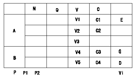
0000001801 POTENTIOMETER ADJUSTMENT
Boost pressure P1kPa {P2 mmHg}
Switch voltage is the value when the idle lever position is 0 V.
* Adjusting method of the 1 potentiometer (P/M)
Substitute the actual measurement of the angle a of each I/P in the following formula and determine the P/M output adjustment y (V).
When the angle a <= c: y = 7.23
When c < angle a < d: y = 7.23+( angle a -33) x 0.133
When d <alpha <e: y=7.97
Reference: Idle position and full speed position output voltages are V6 (idle) and V7 (full speed).
A:Potentiometer standards
B:ON, OFF switch standard
G:ON-->OFF
D:OFF-->ON
E:Adjusting point
F:Checking point
P:Boost pressure
Vi:Applied voltage
C1:Full-speed
C2:Idle
Q:Injection quantity
N:Pump speed
V:Output voltage
C:Control lever angle
----------
a=MEASURE c=33deg d=39deg e=-deg P1=-kPa P2=-mmHg V6=1.6+-0.6V V7=7.6+-0.4V
----------
V1=y+-0.03V V2=1.6+-0.6V V3=-V V4=-V V5=-V C3=0.1~10.2deg C4=(19.4)deg Vi=10V P1=-kPa P2=-mmHg
----------
a=MEASURE c=33deg d=39deg e=-deg P1=-kPa P2=-mmHg V6=1.6+-0.6V V7=7.6+-0.4V
----------
V1=y+-0.03V V2=1.6+-0.6V V3=-V V4=-V V5=-V C3=0.1~10.2deg C4=(19.4)deg Vi=10V P1=-kPa P2=-mmHg
Information:
3. Remove nuts (1) and the bearing caps. Push the rods and pistons up until the rings are out of the cylinder liners. 4. Remove pistons (2) and connecting rod from the cylinder liners.5. Do Steps 1 through 4 for the remainder of the pistons.Install Pistons
1. Put clean engine oil on piston rings, connecting rod bearings and cylinder liners.
Never install the ring compressor on the piston unless the cylinder liner is used as a guide. Damage to the piston rings can be the result.
2. Use tool (A) and install pistons (1) and connecting rods in the cylinder liner. Be sure the number on the tab groove side of the connecting rod is on the opposite side from the camshaft.3. Install the bearing caps on the connecting rods with number on side of the bearing caps on the same side and same number as on the connecting rod.4. Install the nuts and tighten to a torque of 60 6 lb.ft. (80 8 N m). Put a mark on the nuts and caps and tighten nuts an extra 120°.5. Do Steps 1 through 4 for the remainder of the pistons.end by:a) install oil pumpb) install cylinder headDisassemble And Assemble Pistons
start by:a) remove pistons 1. Remove bearings (2) from the connecting rod and connecting rod cap.2. Remove retainer ring (1). Remove piston pin (3) from the piston and connecting rod. 3. Use tool (A) to remove the piston rings (4) from the piston. 4. Heat the connecting rod to a temperature of 350 to 500°F (177 to 260°C). Put connecting rod (6) in position on the base plate of tooling (B). Put a new bearing (5) on the adapter of tooling (B). Put the adapter in position in the connecting rod and base plate of tooling (B). 5. Install the pusher adapter (8) and pusher (7) from tooling (B) on the adapter. The old bearing is pushed out by tooling (B) as the new bearing is installed.6. Use tooling (B) to push the new bearing (5) into the connecting rod (6) until the push adapter of tooling (B) makes full contact with the connecting rod surface. See USE OF PISTON PIN BEARING REMOVAL AND INSTALLATION TOOLS, SPECIAL INSTRUCTION, Form No. SMHS7295. Use tooling (C) for later type connecting rods (tapered ends).7. Check the piston pin bore diameter after the bearing is installed. The correct dimension is 2.0012 .0003 in. (50.830 0.008 mm).8. Clean the ring grooves in the piston before rings are installed. The two compression rings have marks "UP-1" and "UP-2". The rings must be installed with these marks toward the top of the piston with "UP-1" as the top ring. After installation of all three piston rings, put piston rings in position so gaps in rings are 120° apart. 9. Use tool (A) to install the piston rings on the piston. 10. Install bearings (2) in the connecting rod and connecting rod cap. Be sure the tabs in back of bearings are in the tab
Have questions with 104745-9003?
Group cross 104745-9003 ZEXEL
Nissan-Diesel
Nissan-Diesel
Nissan
104745-9003
9 460 611 962
167006T016
INJECTION-PUMP ASSEMBLY
TD27
TD27
Nissan-Diesel
104745-9003
9 460 611 962
167006T016
INJECTION-PUMP ASSEMBLY
TD27
TD27