Information injection-pump assembly
ZEXEL
104745-9001
1047459001
Rating:
Cross reference number
ZEXEL
104745-9001
1047459001
Zexel num
Bosch num
Firm num
Name
104745-9001
INJECTION-PUMP ASSEMBLY
Calibration Data:
Adjustment conditions
Test oil
1404 Test oil ISO4113orSAEJ967d
1404 Test oil ISO4113orSAEJ967d
Test oil temperature
degC
45
45
50
Nozzle
105780-0060
Bosch type code
NP-DN0SD1510
Nozzle holder
105780-2150
Opening pressure
MPa
13
13
13.3
Opening pressure
kgf/cm2
133
133
136
Injection pipe
157805-7320
Injection pipe
Inside diameter - outside diameter - length (mm) mm 2-6-450
Inside diameter - outside diameter - length (mm) mm 2-6-450
Joint assembly
157641-4720
Tube assembly
157641-4020
Transfer pump pressure
kPa
20
20
20
Transfer pump pressure
kgf/cm2
0.2
0.2
0.2
Direction of rotation (viewed from drive side)
Right R
Right R
Injection timing adjustment
Pump speed
r/min
1100
1100
1100
Average injection quantity
mm3/st.
49.9
49.4
50.4
Difference in delivery
mm3/st.
4
Basic
*
Oil temperature
degC
50
48
52
Injection timing adjustment_02
Pump speed
r/min
500
500
500
Average injection quantity
mm3/st.
41.3
38.8
43.8
Oil temperature
degC
48
46
50
Injection timing adjustment_03
Pump speed
r/min
1100
1100
1100
Average injection quantity
mm3/st.
49.9
48.9
50.9
Difference in delivery
mm3/st.
4.5
Basic
*
Oil temperature
degC
50
48
52
Injection timing adjustment_04
Pump speed
r/min
2150
2150
2150
Average injection quantity
mm3/st.
46.3
43.8
48.8
Oil temperature
degC
52
50
54
Injection quantity adjustment
Pump speed
r/min
2550
2550
2550
Average injection quantity
mm3/st.
10.9
8.9
12.9
Difference in delivery
mm3/st.
3
Basic
*
Oil temperature
degC
55
52
58
Injection quantity adjustment_02
Pump speed
r/min
2700
2700
2700
Average injection quantity
mm3/st.
5
Oil temperature
degC
55
52
58
Injection quantity adjustment_03
Pump speed
r/min
2350
2350
2350
Average injection quantity
mm3/st.
39.7
39.7
39.7
Oil temperature
degC
52
50
54
Injection quantity adjustment_04
Pump speed
r/min
2550
2550
2550
Average injection quantity
mm3/st.
10.9
8.4
13.4
Basic
*
Oil temperature
degC
55
52
58
Governor adjustment
Pump speed
r/min
350
350
350
Average injection quantity
mm3/st.
7.7
5.7
9.7
Difference in delivery
mm3/st.
2
Basic
*
Oil temperature
degC
48
46
50
Governor adjustment_02
Pump speed
r/min
350
350
350
Average injection quantity
mm3/st.
7.7
5.2
10.2
Difference in delivery
mm3/st.
2.5
Basic
*
Oil temperature
degC
48
46
50
Timer adjustment
Pump speed
r/min
100
100
100
Average injection quantity
mm3/st.
60
45
80
Basic
*
Oil temperature
degC
48
46
50
Remarks
Full
Full
Timer adjustment_02
Pump speed
r/min
100
100
100
Average injection quantity
mm3/st.
60
45
80
Oil temperature
degC
48
46
50
Remarks
Full
Full
Speed control lever angle
Pump speed
r/min
350
350
350
Average injection quantity
mm3/st.
0
0
0
Oil temperature
degC
48
46
50
Remarks
Magnet OFF at idling position
Magnet OFF at idling position
0000000901
Pump speed
r/min
1100
1100
1100
Overflow quantity
cm3/min
390
260
520
Oil temperature
degC
50
48
52
Stop lever angle
Pump speed
r/min
1100
1100
1100
Pressure
kPa
431
402
460
Pressure
kgf/cm2
4.4
4.1
4.7
Basic
*
Oil temperature
degC
50
48
52
Stop lever angle_02
Pump speed
r/min
1100
1100
1100
Pressure
kPa
431
392
470
Pressure
kgf/cm2
4.4
4
4.8
Basic
*
Oil temperature
degC
50
48
52
Stop lever angle_03
Pump speed
r/min
1700
1700
1700
Pressure
kPa
559
520
598
Pressure
kgf/cm2
5.7
5.3
6.1
Oil temperature
degC
50
48
52
0000001101
Pump speed
r/min
1100
1100
1100
Timer stroke
mm
1.9
1.7
2.1
Basic
*
Oil temperature
degC
50
48
52
_02
Pump speed
r/min
850
850
850
Timer stroke
mm
0.5
0
1
Oil temperature
degC
50
48
52
_03
Pump speed
r/min
1100
1100
1100
Timer stroke
mm
1.9
1.6
2.2
Basic
*
Oil temperature
degC
50
48
52
_04
Pump speed
r/min
1700
1700
1700
Timer stroke
mm
4.4
3.9
4.9
Oil temperature
degC
50
48
52
_05
Pump speed
r/min
2300
2300
2300
Timer stroke
mm
6.1
5.6
6.5
Oil temperature
degC
52
50
54
0000001201
Max. applied voltage
V
8
8
8
Test voltage
V
13
12
14
0000001401
Pump speed
r/min
1100
1100
1100
Average injection quantity
mm3/st.
31
30.5
31.5
Timer stroke TA
mm
1.2
1
1.4
Timer stroke variation dT
mm
0.7
0.7
0.7
Basic
*
Oil temperature
degC
50
48
52
_02
Pump speed
r/min
1100
1100
1100
Average injection quantity
mm3/st.
31
30
32
Timer stroke TA
mm
1.2
0.9
1.5
Basic
*
Oil temperature
degC
50
48
52
_03
Pump speed
r/min
1100
1100
1100
Average injection quantity
mm3/st.
22
19.5
24.5
Timer stroke TA
mm
0.6
0.1
1.1
Oil temperature
degC
50
48
52
Timing setting
K dimension
mm
3.3
3.2
3.4
KF dimension
mm
5.8
5.7
5.9
MS dimension
mm
0.9
0.8
1
Pre-stroke
mm
0.1
0.08
0.12
Control lever angle alpha
deg.
25
23
27
Control lever angle beta
deg.
36
31
41
Test data Ex:
0000001801 POTENTIOMETER ADJUSTMENT
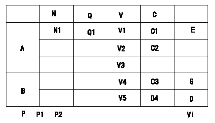
Potentiometer adjustment
1. Applied voltage: Vi
2. Boost pressure = P1kPa {P2 mmHg}
3. Set the control lever at the adjusting point. Position the dummy bolt against the lever and fix.
4. Assemble the potentiometer to obtain output voltage V1 (V) at the fixed position.
5. After mounting the potentiometer, remove the dummy bolt.
At TCV duty 100%
A:Adjusting point
B:Performance standards
C:Control lever angle
N:Pump speed
V:Output voltage
Q:Injection quantity
C1:Idle
C2:Full speed
----------
----------
N1=-r/min Q1=-cm3/1,000st V1=1.6+-0.03V V2=7.6+-1.1V V3=-V V4=-V V5=-V C3=(4.9+-2.5)deg C4=(19.4+-4)deg P1=-kPa P2=-mmHg Vi=10V
----------
----------
N1=-r/min Q1=-cm3/1,000st V1=1.6+-0.03V V2=7.6+-1.1V V3=-V V4=-V V5=-V C3=(4.9+-2.5)deg C4=(19.4+-4)deg P1=-kPa P2=-mmHg Vi=10V
Information:
start by: a) remove oil pump1. Check the connecting rods and caps for their identification and location.2. Turn crankshaft until connecting rod caps are in position shown. 3. Remove the nuts (1) and the cap from connecting rod. Remove lower half of bearing from cap.4. Push the connecting rod away from the crankshaft. Remove the upper half of bearing from connecting rod. Install the bearings dry when the clearance checks are made. Put clean engine oil on the bearings for final assembly.5. Install upper half of bearing in connecting rod.6. Pull the connecting rod slowly on to the crankshaft.7. Install lower half of bearing in cap. Be sure the tabs in back of bearings are in the tab grooves of connecting rod and cap.
Do not use an impact wrench to tighten the bolts the additional 120° 5°.
8. Use Plastigage (A) to check bearing clearance.9. Put Plastigage (A) on the bearing.10. Put clean engine oil on threads of rod bolts and seat surfaces of nuts. Be sure the cylinder numbers on the rod cap and rod are the same and are on the same side of the connecting rod. Numbers are on the same side of rod and caps as are the grooves for the bearing tabs. If new rods are installed, put the cylinder number on the rod and cap. Do not turn the crankshaft when Plastigage (A) is in position. 11. Install the rod caps (2). Install the nuts. Tighten each nut to a torque of 60 6 lb. ft. (80 8 N m). Put a mark on the nuts and cap and tighten nuts an extra 120° 5° from the mark. Remove the rod cap. Remove Plastigage (A) and check the bearing clearance. The bearing clearance must be .0028 to .0066 in. (0.071 to 0.168 mm) for new bearings. Maximum clearance with used bearings is .010 in. (0.25 mm).12. Put clean engine oil on lower half of bearing. Install rod cap again. Tighten each nut to 60 6 lb.ft. (80 8 N m). Put a mark on nuts and cap and tighten nuts an extra 120° 5° from mark.13. Do Steps 1 through 12 for remainder of connecting rod bearings.end by:a) install oil pump
Have questions with 104745-9001?
Group cross 104745-9001 ZEXEL
Nissan-Diesel
104745-9001
INJECTION-PUMP ASSEMBLY