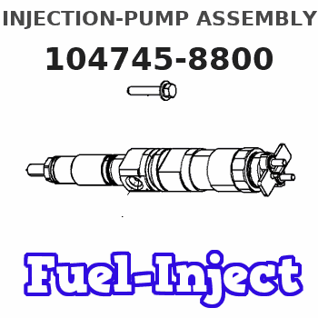
Information injection-pump assembly
ZEXEL
104745-8800
1047458800
Rating:
Cross reference number
ZEXEL
104745-8800
1047458800
Zexel num
Bosch num
Firm num
Name
104745-8800
INJECTION-PUMP ASSEMBLY
11CJ VE4 VE
11CJ VE4 VE
Calibration Data:
Adjustment conditions
Test oil
1404 Test oil ISO4113orSAEJ967d
1404 Test oil ISO4113orSAEJ967d
Test oil temperature
degC
45
45
50
Nozzle
105780-0060
Bosch type code
NP-DN0SD1510
Nozzle holder
105780-2150
Opening pressure
MPa
13
13
13.3
Opening pressure
kgf/cm2
133
133
136
Injection pipe
157805-7320
Injection pipe
Inside diameter - outside diameter - length (mm) mm 2-6-450
Inside diameter - outside diameter - length (mm) mm 2-6-450
Joint assembly
157641-4720
Tube assembly
157641-4020
Transfer pump pressure
kPa
20
20
20
Transfer pump pressure
kgf/cm2
0.2
0.2
0.2
Direction of rotation (viewed from drive side)
Right R
Right R
Injection timing adjustment
Pump speed
r/min
1000
1000
1000
Average injection quantity
mm3/st.
55.4
54.9
55.9
Difference in delivery
mm3/st.
4.5
Basic
*
Oil temperature
degC
50
48
52
Injection timing adjustment_02
Pump speed
r/min
600
600
600
Average injection quantity
mm3/st.
47.7
45.2
50.2
Oil temperature
degC
48
46
50
Injection timing adjustment_03
Pump speed
r/min
1000
1000
1000
Average injection quantity
mm3/st.
55.4
54.4
56.4
Difference in delivery
mm3/st.
5
Basic
*
Oil temperature
degC
50
48
52
Injection timing adjustment_04
Pump speed
r/min
1500
1500
1500
Average injection quantity
mm3/st.
53.4
50.9
55.9
Oil temperature
degC
50
48
52
Injection timing adjustment_05
Pump speed
r/min
2000
2000
2000
Average injection quantity
mm3/st.
57
53.5
60.5
Oil temperature
degC
50
48
52
Injection quantity adjustment
Pump speed
r/min
2475
2475
2475
Average injection quantity
mm3/st.
18.5
15.5
21.5
Difference in delivery
mm3/st.
5.5
Basic
*
Oil temperature
degC
52
50
54
Injection quantity adjustment_02
Pump speed
r/min
2800
2800
2800
Average injection quantity
mm3/st.
5
Oil temperature
degC
55
52
58
Injection quantity adjustment_03
Pump speed
r/min
2475
2475
2475
Average injection quantity
mm3/st.
18.5
13.5
23.5
Difference in delivery
mm3/st.
6
Basic
*
Oil temperature
degC
52
50
54
Governor adjustment
Pump speed
r/min
350
350
350
Average injection quantity
mm3/st.
13.4
11.4
15.4
Difference in delivery
mm3/st.
2
Basic
*
Oil temperature
degC
48
46
50
Governor adjustment_02
Pump speed
r/min
350
350
350
Average injection quantity
mm3/st.
13.4
10.9
15.9
Difference in delivery
mm3/st.
2.5
Basic
*
Oil temperature
degC
48
46
50
Governor adjustment_03
Pump speed
r/min
750
750
750
Average injection quantity
mm3/st.
5
Oil temperature
degC
50
48
52
Timer adjustment
Pump speed
r/min
150
150
150
Average injection quantity
mm3/st.
46
36
56
Basic
*
Oil temperature
degC
48
46
50
Remarks
IDLE
IDLE
Timer adjustment_02
Pump speed
r/min
150
150
150
Average injection quantity
mm3/st.
46
36
56
Oil temperature
degC
48
46
50
Remarks
IDLE
IDLE
Speed control lever angle
Pump speed
r/min
350
350
350
Average injection quantity
mm3/st.
0
0
0
Oil temperature
degC
48
46
50
Remarks
Magnet OFF at idling position
Magnet OFF at idling position
0000000901
Pump speed
r/min
1250
1250
1250
Overflow quantity
cm3/min
800
670
930
Oil temperature
degC
50
48
52
Stop lever angle
Pump speed
r/min
1250
1250
1250
Pressure
kPa
579
559
599
Pressure
kgf/cm2
5.9
5.7
6.1
Basic
*
Oil temperature
degC
50
48
52
0000001101
Pump speed
r/min
1250
1250
1250
Timer stroke
mm
4.9
4.7
5.1
Basic
*
Oil temperature
degC
50
48
52
_02
Pump speed
r/min
700
700
700
Timer stroke
mm
2.4
1.8
3
Oil temperature
degC
50
48
52
_03
Pump speed
r/min
1250
1250
1250
Timer stroke
mm
4.9
4.5
5.3
Basic
*
Oil temperature
degC
50
48
52
_04
Pump speed
r/min
2000
2000
2000
Timer stroke
mm
7.4
6.9
7.8
Oil temperature
degC
50
48
52
0000001201
Max. applied voltage
V
8
8
8
Test voltage
V
13
12
14
0000001501
Pump speed
r/min
1000
1000
1000
Height
m
2000
2000
2000
Atmospheric pressure difference
kPa
-21.9
-21.9
-21.9
Atmospheric pressure difference
mmHg
-164
-164
-164
Average injection quantity
mm3/st.
48.8
47.3
50.3
Decrease qty
mm3/st.
6.6
6.6
6.6
Decrease rate
%
12
12
12
Basic
*
Oil temperature
degC
50
48
52
_02
Pump speed
r/min
1000
1000
1000
Height
m
0
0
0
Atmospheric pressure difference
kPa
0
0
0
Atmospheric pressure difference
mmHg
0
0
0
Average injection quantity
mm3/st.
55.4
54.4
56.4
Oil temperature
degC
50
48
52
_03
Pump speed
r/min
1000
1000
1000
Height
m
500
500
500
Atmospheric pressure difference
kPa
-5.9
-9.2
-2.6
Atmospheric pressure difference
mmHg
44
19
69
Average injection quantity
mm3/st.
55.4
55.4
55.4
Oil temperature
degC
50
48
52
_04
Pump speed
r/min
1000
1000
1000
Height
m
2000
2000
2000
Atmospheric pressure difference
kPa
-21.9
-21.9
-21.9
Atmospheric pressure difference
mmHg
-164
-164
-164
Average injection quantity
mm3/st.
48.8
46.8
50.8
Basic
*
Oil temperature
degC
50
48
52
Timing setting
K dimension
mm
3.3
3.2
3.4
KF dimension
mm
5.8
5.7
5.9
MS dimension
mm
1.1
1
1.2
Control lever angle alpha
deg.
59
55
63
Control lever angle beta
deg.
42
37
47
Test data Ex:
0000001801 V-FICD ADJUSTMENT
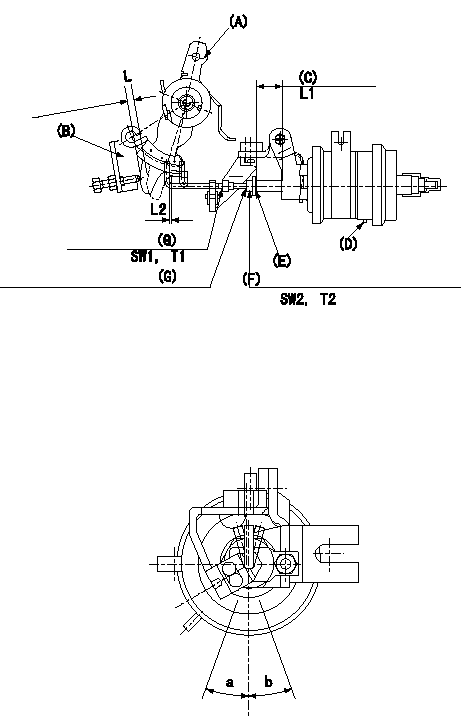
Standards for adjusting the double stage actuator
(A) Control lever
(B): Idle set bracket
(C): Actuator stroke = L1
(D): Negative pressure inlet
(E): Stroke adjusting screw
(F): Stroke adjusting nut
(G): Rod position adjusting nut
L:Thickness of the shim
Actuator adjustment
(1)Mount the actuator to the injection pump.
(2)Position the control lever in the idling position.
(3)Adjust with the nut (G) so that the space between the control lever and the rod is L2.
(4)Insert a shim with thickness of L between the lever (A) and the bracket (B).
(5)At that time, adjust with the screw (E) and fix with the nut (F) so that the actuator stroke (C) is the full stroke [with P applied to the negative pressure inlet port (D)].
(6)Allowable angle when adjusting the rod position: c
----------
L1=12.5(mm) L2=1+1(mm) L3=12.1+-0.05(mm) P=-66.7kPa(-500mmHg) c=+-20(deg)
----------
a=20(deg) b=20(deg) L=12.1+-0.05mm L1=12.5mm L2=1+1mm T1=1.4~2.0N-m(0.14~0.2kgf-m) T2=3.4~4.9N-m(0.35~0.5kgf-m) SW1=SW7 SW2=SW8
----------
L1=12.5(mm) L2=1+1(mm) L3=12.1+-0.05(mm) P=-66.7kPa(-500mmHg) c=+-20(deg)
----------
a=20(deg) b=20(deg) L=12.1+-0.05mm L1=12.5mm L2=1+1mm T1=1.4~2.0N-m(0.14~0.2kgf-m) T2=3.4~4.9N-m(0.35~0.5kgf-m) SW1=SW7 SW2=SW8
Information:
b. Operate vehicle at 60% of rated speed with moderate load until oil and coolant temperatures reach their normal range for operation. If there is a heavy vibration, drive shaft whip, tire bounce, etc., do not continue with dynamometer test until cause of the problem is corrected. Engines that have had new internal parts installed should be operated on a run-in schedule before operation at full load. For run-in schedule information, make reference to General Instructions section of this Service Manual.2. Put transmission in direct gear and the differential in the highest speed ratio. Operate vehicle at maximum engine speed and increase chassis dynamometer load until a speed of 50 rpm less than rated speed is reached (continuity light should be on). Maintain this speed for one minute and record the engine speed and wheel horsepower. If horsepower is low and poor maintenance is suspected, remove air cleaner or inlet piping to turbocharger and check horsepower again to see if a plugged air cleaner could be the problem.3a. If the wheel horsepower is correct, find the balance point of the engine (speed at which the rack adjustment screw just touches the torque spring or stop bar). At this point the continuity light should flicker (go off and on dimly). If the balance point is correct, then the low power complaint can not be validated. No further test or repairs are necessary.If the balance point is low, see Procedure No. 5.3b. If the wheel horsepower is below the correct value, find the balance point of the engine (speed at which the rack adjustment screw just touches the torque spring or stop bar). At this point the continuity light should flicker (go off and on dimly). If the balance point is correct, see Procedure No. 6If the balance point is low, see Procedure No. 4.4. Stop the engine. Remove the AFRC (air-fuel ratio control). Put a cover over the hole where the AFRC was installed. Start the engine and check the balance point and horsepower again. If both of these are now correct, the problem is in AFRC. Repair or replace the AFRC. If, with the AFRC removed, horsepower is now acceptable and balance point is low, the problem is still with AFRC. Repair or replace the AFRC. Then adjust balance point according to Procedure No. 5.5. If the balance point is low, the high idle will have to be increased to raise the balance point to the correct rpm (the point at which the continuity light just comes on). If the balance point is still low and high idle has been adjusted to maximum, disengage clutch while maximum throttle position is maintained. Now observe high idle rpm and, if lower than previously adjusted, check frame-to-engine-mount. A damaged or loose engine mount may put the linkage in a bind and thus prevent maximum governor position at load conditions.6. If the balance point was correct and the wheel horsepower was low, install the 4S6553 Engine Test Group and do the wheel
Have questions with 104745-8800?
Group cross 104745-8800 ZEXEL
104745-8800
INJECTION-PUMP ASSEMBLY