Information injection-pump assembly
BOSCH
9 460 614 531
9460614531
ZEXEL
104745-8271
1047458271
MITSUBISHI
MD334895
md334895
Rating:
Cross reference number
BOSCH
9 460 614 531
9460614531
ZEXEL
104745-8271
1047458271
MITSUBISHI
MD334895
md334895
Zexel num
Bosch num
Firm num
Name
104745-8271
9 460 614 531
MD334895 MITSUBISHI
INJECTION-PUMP ASSEMBLY
4D56 K
4D56 K
Calibration Data:
Adjustment conditions
Test oil
1404 Test oil ISO4113orSAEJ967d
1404 Test oil ISO4113orSAEJ967d
Test oil temperature
degC
45
45
50
Nozzle
105780-0060
Bosch type code
NP-DN0SD1510
Nozzle holder
105780-2150
Opening pressure
MPa
13
13
13.3
Opening pressure
kgf/cm2
133
133
136
Injection pipe
157805-7320
Injection pipe
Inside diameter - outside diameter - length (mm) mm 2-6-450
Inside diameter - outside diameter - length (mm) mm 2-6-450
Joint assembly
157641-4720
Tube assembly
157641-4020
Transfer pump pressure
kPa
20
20
20
Transfer pump pressure
kgf/cm2
0.2
0.2
0.2
Direction of rotation (viewed from drive side)
Right R
Right R
Injection timing adjustment
Pump speed
r/min
750
750
750
Boost pressure
kPa
0
0
0
Boost pressure
mmHg
0
0
0
Average injection quantity
mm3/st.
52.6
52.1
53.1
Difference in delivery
mm3/st.
4
Basic
*
Oil temperature
degC
50
48
52
Remarks
NA
NA
Injection timing adjustment_02
Pump speed
r/min
750
750
750
Boost pressure
kPa
44
42.7
45.3
Boost pressure
mmHg
330
320
340
Average injection quantity
mm3/st.
62.6
62.1
63.1
Difference in delivery
mm3/st.
5
Basic
*
Oil temperature
degC
50
48
52
Remarks
CBS
CBS
Injection timing adjustment_03
Pump speed
r/min
1250
1250
1250
Boost pressure
kPa
73.3
72
74.6
Boost pressure
mmHg
550
540
560
Average injection quantity
mm3/st.
76.6
76.1
77.1
Difference in delivery
mm3/st.
6
Basic
*
Oil temperature
degC
50
48
52
Remarks
Full
Full
Injection timing adjustment_04
Pump speed
r/min
750
750
750
Boost pressure
kPa
0
0
0
Boost pressure
mmHg
0
0
0
Average injection quantity
mm3/st.
52.6
51.6
53.6
Basic
*
Oil temperature
degC
50
48
52
Remarks
NA
NA
Injection timing adjustment_05
Pump speed
r/min
750
750
750
Boost pressure
kPa
44
42.7
45.3
Boost pressure
mmHg
330
320
340
Average injection quantity
mm3/st.
62.6
61.6
63.6
Basic
*
Oil temperature
degC
50
48
52
Remarks
CBS
CBS
Injection timing adjustment_06
Pump speed
r/min
1000
1000
1000
Boost pressure
kPa
73.3
72
74.6
Boost pressure
mmHg
550
540
560
Average injection quantity
mm3/st.
77
74.5
79.5
Oil temperature
degC
50
48
52
Injection timing adjustment_07
Pump speed
r/min
1250
1250
1250
Boost pressure
kPa
73.3
72
74.6
Boost pressure
mmHg
550
540
560
Average injection quantity
mm3/st.
76.6
75.6
77.6
Difference in delivery
mm3/st.
6.5
Basic
*
Oil temperature
degC
50
48
52
Remarks
Full
Full
Injection timing adjustment_08
Pump speed
r/min
2100
2100
2100
Boost pressure
kPa
73.3
72
74.6
Boost pressure
mmHg
550
540
560
Average injection quantity
mm3/st.
65
62.5
67.5
Oil temperature
degC
52
50
54
Injection quantity adjustment
Pump speed
r/min
2650
2650
2650
Boost pressure
kPa
73.3
72
74.6
Boost pressure
mmHg
550
540
560
Average injection quantity
mm3/st.
27.9
24.9
30.9
Difference in delivery
mm3/st.
8.5
Basic
*
Oil temperature
degC
55
52
58
Injection quantity adjustment_02
Pump speed
r/min
2950
2950
2950
Boost pressure
kPa
73.3
72
74.6
Boost pressure
mmHg
550
540
560
Average injection quantity
mm3/st.
5
Oil temperature
degC
55
52
58
Injection quantity adjustment_03
Pump speed
r/min
2650
2650
2650
Boost pressure
kPa
73.3
72
74.6
Boost pressure
mmHg
550
540
560
Average injection quantity
mm3/st.
27.9
22.9
32.9
Difference in delivery
mm3/st.
9
Basic
*
Oil temperature
degC
55
52
58
Governor adjustment
Pump speed
r/min
375
375
375
Boost pressure
kPa
0
0
0
Boost pressure
mmHg
0
0
0
Average injection quantity
mm3/st.
19.4
17.9
20.9
Difference in delivery
mm3/st.
2
Basic
*
Oil temperature
degC
48
46
50
Governor adjustment_02
Pump speed
r/min
375
375
375
Boost pressure
kPa
0
0
0
Boost pressure
mmHg
0
0
0
Average injection quantity
mm3/st.
19.4
17.4
21.4
Difference in delivery
mm3/st.
2.5
Basic
*
Oil temperature
degC
48
46
50
Governor adjustment_03
Pump speed
r/min
750
750
750
Boost pressure
kPa
0
0
0
Boost pressure
mmHg
0
0
0
Average injection quantity
mm3/st.
8
Oil temperature
degC
50
48
52
Boost compensator adjustment
Pump speed
r/min
900
900
900
Boost pressure
kPa
0
0
0
Boost pressure
mmHg
0
0
0
Average injection quantity
mm3/st.
7.7
7.7
7.7
Oil temperature
degC
50
48
52
Lever angle (shim thickness)
mm
9.6
9.6
9.6
Timer adjustment
Pump speed
r/min
100
100
100
Boost pressure
kPa
0
0
0
Boost pressure
mmHg
0
0
0
Average injection quantity
mm3/st.
75
65
85
Basic
*
Oil temperature
degC
48
46
50
Remarks
IDLE
IDLE
Timer adjustment_02
Pump speed
r/min
100
100
100
Boost pressure
kPa
0
0
0
Boost pressure
mmHg
0
0
0
Average injection quantity
mm3/st.
75
65
85
Oil temperature
degC
48
46
50
Remarks
IDLE
IDLE
Speed control lever angle
Pump speed
r/min
375
375
375
Boost pressure
kPa
0
0
0
Boost pressure
mmHg
0
0
0
Average injection quantity
mm3/st.
0
0
0
Oil temperature
degC
48
46
50
Remarks
Magnet OFF at idling position
Magnet OFF at idling position
0000000901
Pump speed
r/min
1250
1250
1250
Boost pressure
kPa
73.3
72
74.6
Boost pressure
mmHg
550
540
560
Overflow quantity
cm3/min
420
290
550
Oil temperature
degC
50
48
52
Stop lever angle
Pump speed
r/min
1250
1250
1250
Boost pressure
kPa
73.3
72
74.6
Boost pressure
mmHg
550
540
560
Pressure
kPa
549
520
578
Pressure
kgf/cm2
5.6
5.3
5.9
Basic
*
Oil temperature
degC
50
48
52
0000001101
Pump speed
r/min
1250
1250
1250
Boost pressure
kPa
73.3
72
74.6
Boost pressure
mmHg
550
540
560
Timer stroke
mm
4.6
4.4
4.8
Basic
*
Oil temperature
degC
50
48
52
_02
Pump speed
r/min
500
500
500
Boost pressure
kPa
73.3
72
74.6
Boost pressure
mmHg
550
540
560
Timer stroke
mm
1.2
0.6
1.8
Oil temperature
degC
48
46
50
_03
Pump speed
r/min
1000
1000
1000
Boost pressure
kPa
73.3
72
74.6
Boost pressure
mmHg
550
540
560
Timer stroke
mm
3.5
2.9
4.1
Oil temperature
degC
50
48
52
_04
Pump speed
r/min
1250
1250
1250
Boost pressure
kPa
73.3
72
74.6
Boost pressure
mmHg
550
540
560
Timer stroke
mm
4.6
4.2
5
Basic
*
Oil temperature
degC
50
48
52
_05
Pump speed
r/min
1500
1500
1500
Boost pressure
kPa
73.3
72
74.6
Boost pressure
mmHg
550
540
560
Timer stroke
mm
5.6
5
6.2
Oil temperature
degC
50
48
52
_06
Pump speed
r/min
2100
2100
2100
Boost pressure
kPa
73.3
72
74.6
Boost pressure
mmHg
550
540
560
Timer stroke
mm
7.8
7.2
8.4
Oil temperature
degC
52
50
54
0000001201
Max. applied voltage
V
8
8
8
Test voltage
V
13
12
14
0000001401
Pump speed
r/min
1250
1250
1250
Boost pressure
kPa
73.3
72
74.6
Boost pressure
mmHg
550
540
560
Average injection quantity
mm3/st.
48
47.5
48.5
Timer stroke TA
mm
3.9
3.7
4.1
Timer stroke variation dT
mm
0.7
0.7
0.7
Basic
*
Oil temperature
degC
50
48
52
_02
Pump speed
r/min
1250
1250
1250
Boost pressure
kPa
73.3
72
74.6
Boost pressure
mmHg
550
540
560
Average injection quantity
mm3/st.
48
47
49
Timer stroke TA
mm
3.9
3.5
4.3
Timer stroke variation dT
mm
0.7
0.7
0.7
Basic
*
Oil temperature
degC
50
48
52
_03
Pump speed
r/min
1250
1250
1250
Boost pressure
kPa
73.3
72
74.6
Boost pressure
mmHg
550
540
560
Average injection quantity
mm3/st.
32
31
33
Timer stroke TA
mm
2.5
1.9
3.1
Timer stroke variation dT
mm
2.1
2.1
2.1
Oil temperature
degC
50
48
52
Timing setting
K dimension
mm
3.3
3.2
3.4
KF dimension
mm
5.8
5.7
5.9
MS dimension
mm
1.2
1.1
1.3
BCS stroke
mm
5.7
5.5
5.9
Control lever angle alpha
deg.
59
55
63
Control lever angle beta
deg.
42
37
47
Test data Ex:
0000001801 W-CSD ADJUSTMENT
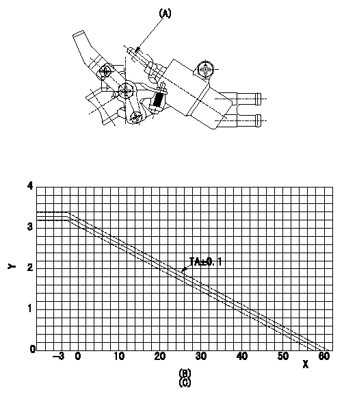
Adjustment of the W-CSD
1. Adjustment of the advance angle of the timer
(1)Determine the timer advance angle using the following graph.
(2)(1) Adjust with the screw (A) so that the timer advance angle determined in the item (1) is obtained.
X:Temperature t (deg C)
Y:Timer stroke TA (mm)
(B): Timer stroke TA (mm):
----------
----------
(C)=TA=-0.0526t+3.14(-3<=t)
----------
----------
(C)=TA=-0.0526t+3.14(-3<=t)
0000001901 W-FICD LEVER ADJUSTMENT
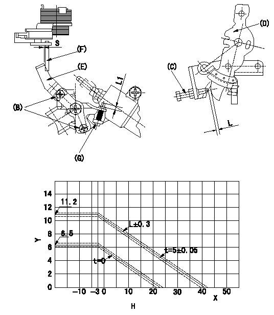
2. Adjustment of the W-FICD
(1)Insert a block gauge L determined from the graph below between the control lever (D) and the idling stopper bolt (C).
(2)Insert a shim S between the W-FICD lever (E) and the control lever (F). Adjust the W-FICD lever (E) so that it contacts the control lever (F) and fix it using bolt (B).
TT
Note:
a) The temperature of wax at the time of adjustment must not exceed a.
b) After completion of the adjustment, confirm that allowance for adjustment of the screw (G) is at least L1.
Y:Control lever L mm
X:Temperature t (deg C)
H:Control lever gap: L (mm)
----------
L=L+-0.05mm S=5+-0.05mm T=3.4~4.9N-m(0.35~0.5kgf-m) a=30degC L1=3mm
----------
S=5mm L1=3mm H=L=-0.256t+10.39(-3<=tdegC)(S=5+-0.05mm)
----------
L=L+-0.05mm S=5+-0.05mm T=3.4~4.9N-m(0.35~0.5kgf-m) a=30degC L1=3mm
----------
S=5mm L1=3mm H=L=-0.256t+10.39(-3<=tdegC)(S=5+-0.05mm)
0000002001 V-FICD ADJUSTMENT
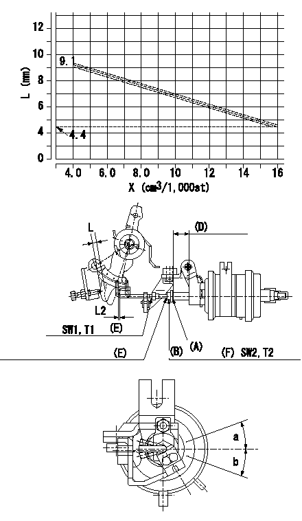
Adjustment of the two stage actuator (FICD).
(C): Stroke adjusting nut
(D): Actuator stroke
(E): Rod position adjusting nut
(F): Stroke adjusting nut
X:Injection quantity
Y:Shim thickness: L
1. Selecting the shim for adjusting the actuator.
(1)Measure the injection quantity at N by inserting the shim L1 between the control lever and the idling stopper bolt.
(2)Select the thickness (L) of the shim for adjusting the actuator using the following formula (refer to the graph.).
Calculation: L
2. Adjustment of the actuator
(1)Mount the actuator to the injection pump.
(2)Position the control lever at the idling position.
(3)Adjust with the nut (D) so that the space between the control lever and the rod becomes L2.
(4)Insert the shim (L) determined above between the control lever and the idling stopper bolt.
(5)Adjust the position of the screw (A) so that the actuator can make its full stroke (Reference value: approx. L3) and fix with the nut (B).
(6)Allowable angle in adjusting the position of the rod: c
----------
N=900r/min L1=6.2mm L:L+-0.1=-0.39167Q+10.667(4.0<=Q<=16.0cm3/1,000st) L2=1+1mm L3=9.6mm c=+-20deg
----------
L2=1+1mm SW1=SW7 T1=1.4~2.0N-m{0.14~0.2kgf-m} SW2=SW8 T2=3.5~5.0N-m{0.35~0.5kgf-m} a=20deg b=20deg
----------
N=900r/min L1=6.2mm L:L+-0.1=-0.39167Q+10.667(4.0<=Q<=16.0cm3/1,000st) L2=1+1mm L3=9.6mm c=+-20deg
----------
L2=1+1mm SW1=SW7 T1=1.4~2.0N-m{0.14~0.2kgf-m} SW2=SW8 T2=3.5~5.0N-m{0.35~0.5kgf-m} a=20deg b=20deg
Information:
The troubleshooting chart provides a definite sequence to be followed for a logical procedure to determine the frequency and amplitude of vibration so that the source of the vibration can be located and corrected.1. The customer must be asked questions to determine whether his complaint is valid, or whether his diagnosis of the actual problem is correct.Some of the questions that must be asked are as follows: a. What components are vibrating?b. In what speed range does this vibration become excessive?c. Does clutch operation affect the vibration?d. What is the history of the problem?2. Run the engine through the idle speed range and note all vibrating components. Look for any loose or broken mounts, brackets, and fasteners. Repair and tighten any fixtures.3. Check idle speed range with clutch disengaged. If vibrations subside, there is a balance problem with the clutch disc. The clutch disc must be repaired or replaced.4. Further analysis requires the use of a vibration instrument. Any instrument which can accurately measure the displacement of the vibration (usually in mils-inch/1000) and the frequency (cycles per second) will be sufficient. A vibration instrument such as the IRD Mechanalysis Model 320 or an equivalent instrument can be used to analyze vibration.5. Measure vibration of cab components which have the objectionable vibration.Run engine slowly through the speed range and measure vibration with the instrument filter OUT. When peak amplitudes are found, run the engine at the speeds they occur and with the instrument filter IN, find the frequency of the vibration.If the frequency of vibration is 1/2 times of engine rpm (1/2 order), the vibration is caused by a cylinder misfiring. This must be corrected before further vibration analysis is made.If the frequency of vibration is 4 times engine rpm, no corrective action can be taken on the engine because this is the firing frequency of the 3408 engine. The problem is in the cab or chassis resonance.If frequency is some order other than 1/2 or 4th, then further measurements must be made on the engine.6. Measurements taken on the engine must be made perpendicular to the crankshaft at the front and rear of the engine in vertical and horizontal directions.7. Record all vibrations over 4.0 mils and the engine rpm at which it occurs (100 rpm intervals are sufficient) with instrument filter OUT. Note any sudden increase and decrease in amplitudes. These occur in resonant speed ranges.If no amplitudes exceed 4.0 mils, the engine is within Caterpillar Specs.If amplitudes exceed 4.0 mils, the vibrations must be measured with the instrument filter IN to obtain the frequency of the vibrations.8. Run the engine at high idle. With the instrument filter IN, check the frequency range and record any amplitudes over 4.0 mils and the corresponding frequency. Analysis of vibrations for the possible causes is done by identifying the frequency of the vibration and where on the engine it is the greatest magnitude. Make reference to Special Instruction, TROUBLESHOOTING ENGINE VIBRATION IN VEHICULAR EQUIPMENT, Form No. SEHS7914 for additional information
Have questions with 104745-8271?
Group cross 104745-8271 ZEXEL
Mitsubishi
Mitsubishi
Mitsubishi
Mitsubishi
Mitsubishi
Mitsubishi
Mitsubishi
Mitsubishi
104745-8271
9 460 614 531
MD334895
INJECTION-PUMP ASSEMBLY
4D56
4D56