Information injection-pump assembly
BOSCH
F 01G 29X 07E
f01g29x07e
ZEXEL
104742-7701
1047427701
YANMAR
12993151020
12993151020

Rating:
Compare Prices: .
As an associate, we earn commssions on qualifying purchases through the links below

Fuel Injection Pump Assembly, Compatible For 4D94LE & Multi-Model Diesel Engines, 104742-7701, 129931-51020, Seamless Direct Replacement(104742-7701)
Sdvbfjnm 【Precise Compatibility】: Compatible For 4D94LE and multi-model diesel engines, validated by OME codes 104742-7701, 129931-51020. || 【OE-Level Integration】: Direct replacement design matches original interfaces without modifications. || 【High-Pressure Durability】: Reinforced construction withstands diesel engine demands long-term reliability. || 【Leak-Proof Design】: Multi-layer sealing technology prevents fuel leaks and corrosion. || 【Code Validation】: Supports diesel fuel systems OME codes 104742-7701, 129931-51020
Sdvbfjnm 【Precise Compatibility】: Compatible For 4D94LE and multi-model diesel engines, validated by OME codes 104742-7701, 129931-51020. || 【OE-Level Integration】: Direct replacement design matches original interfaces without modifications. || 【High-Pressure Durability】: Reinforced construction withstands diesel engine demands long-term reliability. || 【Leak-Proof Design】: Multi-layer sealing technology prevents fuel leaks and corrosion. || 【Code Validation】: Supports diesel fuel systems OME codes 104742-7701, 129931-51020

Fuel Injection Pump 104742-7701 129931-51020 Compatible For Yanmar 4D94LE Engine
GBSCDZAV Accurate fuel injection control makes fuel burn more fully, which not only improves power, but also effectively reduces fuel consumption. || After careful adjustment, the fuel injection quantity can be accurately controlled to ensure that the engine can get the best fuel supply under different working conditions. || Efficient injection pressure can fully atomize fuel, greatly improve combustion efficiency, significantly enhance engine power, and make your car more rapid when accelerating and more stable during driving. || Made of high-quality materials, the internal key components are treated by special technology, ensuring that each fuel injection pump can withstand the test of long-term complex working environment, effectively reducing the probability of failure and prolonging the service life. || Fuel Injection Pump 104742-7701 129931-51020 Compatible For Yanmar 4D94LE Engine
GBSCDZAV Accurate fuel injection control makes fuel burn more fully, which not only improves power, but also effectively reduces fuel consumption. || After careful adjustment, the fuel injection quantity can be accurately controlled to ensure that the engine can get the best fuel supply under different working conditions. || Efficient injection pressure can fully atomize fuel, greatly improve combustion efficiency, significantly enhance engine power, and make your car more rapid when accelerating and more stable during driving. || Made of high-quality materials, the internal key components are treated by special technology, ensuring that each fuel injection pump can withstand the test of long-term complex working environment, effectively reducing the probability of failure and prolonging the service life. || Fuel Injection Pump 104742-7701 129931-51020 Compatible For Yanmar 4D94LE Engine
Fuel Injection Pump Assembly, Compatible For 4D94LE & Multi-Model Diesel Engines, 104742-7701, 129931-51020, Seamless Direct Replacement(129931-51020)
Sdvbfjnm 【Precise Compatibility】: Compatible For 4D94LE and multi-model diesel engines, validated by OME codes 104742-7701, 129931-51020. || 【OE-Level Integration】: Direct replacement design matches original interfaces without modifications. || 【High-Pressure Durability】: Reinforced construction withstands diesel engine demands long-term reliability. || 【Leak-Proof Design】: Multi-layer sealing technology prevents fuel leaks and corrosion. || 【Code Validation】: Supports diesel fuel systems OME codes 104742-7701, 129931-51020
Sdvbfjnm 【Precise Compatibility】: Compatible For 4D94LE and multi-model diesel engines, validated by OME codes 104742-7701, 129931-51020. || 【OE-Level Integration】: Direct replacement design matches original interfaces without modifications. || 【High-Pressure Durability】: Reinforced construction withstands diesel engine demands long-term reliability. || 【Leak-Proof Design】: Multi-layer sealing technology prevents fuel leaks and corrosion. || 【Code Validation】: Supports diesel fuel systems OME codes 104742-7701, 129931-51020
Cross reference number
BOSCH
F 01G 29X 07E
f01g29x07e
ZEXEL
104742-7701
1047427701
YANMAR
12993151020
12993151020
Zexel num
Bosch num
Firm num
Name
104742-7701
F 01G 29X 07E
12993151020 YANMAR
INJECTION-PUMP ASSEMBLY
4TNE94D
4TNE94D
Calibration Data:
Adjustment conditions
Test oil
1404 Test oil ISO4113orSAEJ967d
1404 Test oil ISO4113orSAEJ967d
Test oil temperature
degC
45
45
50
Nozzle
105780-0060
Bosch type code
NP-DN0SD1510
Nozzle holder
105780-2150
Opening pressure
MPa
13
13
13.3
Opening pressure
kgf/cm2
133
133
136
Injection pipe
157805-7320
Injection pipe
Inside diameter - outside diameter - length (mm) mm 2-6-450
Inside diameter - outside diameter - length (mm) mm 2-6-450
Joint assembly
157641-4720
Tube assembly
157641-4020
Transfer pump pressure
kPa
20
20
20
Transfer pump pressure
kgf/cm2
0.2
0.2
0.2
Direction of rotation (viewed from drive side)
Right R
Right R
Injection timing adjustment
Pump speed
r/min
900
900
900
Average injection quantity
mm3/st.
44.8
44.3
45.3
Difference in delivery
mm3/st.
3.5
Basic
*
Oil temperature
degC
50
48
52
Injection timing adjustment_02
Pump speed
r/min
500
500
500
Average injection quantity
mm3/st.
42.2
36.7
47.7
Oil temperature
degC
48
46
50
Injection timing adjustment_03
Pump speed
r/min
750
750
750
Average injection quantity
mm3/st.
46.1
40.6
51.6
Oil temperature
degC
50
48
52
Injection timing adjustment_04
Pump speed
r/min
900
900
900
Average injection quantity
mm3/st.
44.8
43.8
45.8
Difference in delivery
mm3/st.
4
Basic
*
Oil temperature
degC
50
48
52
Injection timing adjustment_05
Pump speed
r/min
1100
1100
1100
Average injection quantity
mm3/st.
45.3
41.3
49.3
Oil temperature
degC
50
48
52
Injection quantity adjustment
Pump speed
r/min
1225
1225
1225
Average injection quantity
mm3/st.
14.4
9.9
18.9
Difference in delivery
mm3/st.
4.5
Basic
*
Oil temperature
degC
50
48
52
Injection quantity adjustment_02
Pump speed
r/min
1400
1400
1400
Average injection quantity
mm3/st.
5
Oil temperature
degC
50
48
52
Injection quantity adjustment_03
Pump speed
r/min
1225
1225
1225
Average injection quantity
mm3/st.
14.4
9.4
19.4
Difference in delivery
mm3/st.
5
Basic
*
Oil temperature
degC
50
48
52
Governor adjustment
Pump speed
r/min
405
405
405
Average injection quantity
mm3/st.
9.1
7.1
11.1
Difference in delivery
mm3/st.
2
Basic
*
Oil temperature
degC
48
46
50
Governor adjustment_02
Pump speed
r/min
405
405
405
Average injection quantity
mm3/st.
9.1
6.6
11.6
Difference in delivery
mm3/st.
2
Basic
*
Oil temperature
degC
48
46
50
Timer adjustment
Pump speed
r/min
100
100
100
Average injection quantity
mm3/st.
53.5
48.5
58.5
Basic
*
Oil temperature
degC
48
46
50
Remarks
Full
Full
Timer adjustment_02
Pump speed
r/min
100
100
100
Average injection quantity
mm3/st.
53.5
48.5
58.5
Oil temperature
degC
48
46
50
Remarks
Full
Full
Speed control lever angle
Pump speed
r/min
405
405
405
Average injection quantity
mm3/st.
0
0
0
Oil temperature
degC
48
46
50
Remarks
Magnet OFF at idling position
Magnet OFF at idling position
0000000901
Pump speed
r/min
1000
1000
1000
Overflow quantity
cm3/min
400
270
530
Oil temperature
degC
50
48
52
Stop lever angle
Pump speed
r/min
1000
1000
1000
Pressure
kPa
461
432
490
Pressure
kgf/cm2
4.7
4.4
5
Basic
*
Oil temperature
degC
50
48
52
Stop lever angle_02
Pump speed
r/min
900
900
900
Pressure
kPa
441
392
490
Pressure
kgf/cm2
4.5
4
5
Oil temperature
degC
50
48
52
Stop lever angle_03
Pump speed
r/min
1000
1000
1000
Pressure
kPa
461
422
500
Pressure
kgf/cm2
4.7
4.3
5.1
Basic
*
Oil temperature
degC
50
48
52
Stop lever angle_04
Pump speed
r/min
1100
1100
1100
Pressure
kPa
481
432
530
Pressure
kgf/cm2
4.9
4.4
5.4
Oil temperature
degC
50
48
52
0000001101
Pump speed
r/min
1000
1000
1000
Timer stroke
mm
0.5
0.3
0.7
Basic
*
Oil temperature
degC
50
48
52
_02
Pump speed
r/min
1000
1000
1000
Timer stroke
mm
0.5
0.1
0.9
Basic
*
Oil temperature
degC
50
48
52
_03
Pump speed
r/min
1100
1100
1100
Timer stroke
mm
1
0.4
1.6
Oil temperature
degC
50
48
52
0000001201
Max. applied voltage
V
8
8
8
Test voltage
V
13
12
14
Timing setting
K dimension
mm
3.1
3
3.2
KF dimension
mm
5.3
5.2
5.4
MS dimension
mm
1.8
1.7
1.9
Control lever angle alpha
deg.
16
12
20
Control lever angle beta
deg.
27
22
32
Test data Ex:
0000001801 STOP LEVER ADJUSTMENT
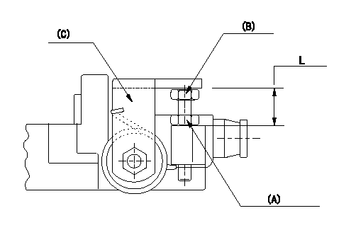
Adjustment of the stop lever
Adjust the bolt (B) so that the starting injection quantity is as specified, then fix using the nut.
(A) Adjusting nut (Torque T)
(B) Adjusting bolt
(C) Starting injection quantity adjusting lever
----------
T=6~9N-m(0.6~0.9kgf-m)
----------
L=15.0~18.5mm
----------
T=6~9N-m(0.6~0.9kgf-m)
----------
L=15.0~18.5mm
Information:
* NA: Naturally Aspirated* T: Turbocharged* TA: Turbocharged, Aftercooled* DI: Direct Injection* PC: Precombustion ChamberThis instruction gives the information needed to install a service replacement fuel injection pump and governor group for the above engines.1 Remove the fuel system from the engine. Make reference to the Service Manual for correct procedure.
When any replacement parts are put in the fuel system, the low idle, high idle and fuel setting must be checked and adjustments made as necessary. Only a mechanic with training in fuel system maintenance must be permitted to make these adjustments. The correct low idle and high idle rpm, and fuel setting are given in the FUEL SETTING INFORMATION.
2 Find and write down the serial number of the machine, the serial number of the engine and the engine arrangement number. All of these numbers are needed to find which parts to use for the fuel system reconditioning. 3 The chart that follows gives the part number of the governor spring (1) that is already installed in each Service Pump Group. Make reference to the FUEL SETTING INFORMATION, to find the part number of the governor spring needed for the fuel system reconditioning. If the governor spring must be changed, the chart for governor spring identification gives a method to find the correct governor spring. See the Service Manual for the procedure needed to change the governor spring. 4 The chart that follows gives the part number of the detent spring that is installed in the governor control of each service group. Look at the Parts Book for the specific engine or machine, to find which detent spring is needed for the fuel system reconditioning. If it is necessary to change detent spring (2), see the Service Manual for the procedure to install the detent spring. The illustrations with steps 4 and 5 show a 4 cylinder engine fuel system only; the procedure is the same for a 6 cylinder engine fuel system. 5 Make a comparison of side cover (3) on the new pump housing in the service group and the side cover on the old pump housing. If the side covers are different, they must be exchanged. The new pump housing must have the same type of side cover that is installed on the old pump housing. Use new gaskets when the side cover is exchanged. 6 Remove cover (4) from the new service group and the similar cover from the old fuel system. If the torque control groups are different, they must be exchanged. The torque control group on the new pump housing must be the same as the torque control group on the old pump housing. 7 The new service group has one bolt (5) and a stud (6) with nut (7) to fasten the torque control group in position. For those earlier fuel systems that had two bolts, similar to bolt (5), and did not have stud (6) and nut (7), use only the one bolt (5) and stud (6) with nut
Have questions with 104742-7701?
Group cross 104742-7701 ZEXEL
Yanmar
104742-7701
F 01G 29X 07E
12993151020
INJECTION-PUMP ASSEMBLY
4TNE94D
4TNE94D