Information injection-pump assembly
ZEXEL
104742-7540
1047427540

Rating:
Compare Prices: .
As an associate, we earn commssions on qualifying purchases through the links below

WZCNLXLX Fuel Injection Pump 129671-51950 12967151950 For Yanmar Marine Engine 4JH4-TE 4JH4-HTE
WZCNLXLX Item Name:Fuel Injection Pump || Item Number:129671-51950, 12967151950, YM129671-51950, YM12967151950 || Application:For Yanmar Marine Engine 4JH4-TE 4JH4-HTE || Note: If you are unsure if the product is suitable.In order not to delay your use of the parts, please provide your engine nameplate or serial number and part number, and we will help you confirm if it is suitable. To avoid unnecessary returns, please check the product image and part number to ensure it is the product you want. || Tip: Please contact us - we are a professional sales team and we have many products to offer to you. Many buyers are very satisfied with our service. You can get first-class products and high-quality services from us, believe me, you will have a pleasant shopping experience here.
WZCNLXLX Item Name:Fuel Injection Pump || Item Number:129671-51950, 12967151950, YM129671-51950, YM12967151950 || Application:For Yanmar Marine Engine 4JH4-TE 4JH4-HTE || Note: If you are unsure if the product is suitable.In order not to delay your use of the parts, please provide your engine nameplate or serial number and part number, and we will help you confirm if it is suitable. To avoid unnecessary returns, please check the product image and part number to ensure it is the product you want. || Tip: Please contact us - we are a professional sales team and we have many products to offer to you. Many buyers are very satisfied with our service. You can get first-class products and high-quality services from us, believe me, you will have a pleasant shopping experience here.
ZGZJYBL Fuel Injection Pump For Yanmar Marine Engine 4JH4-TE 4JH4-HTE 129671-51950 12967151950
ZGZJYBL Item Name:Fuel Injection Pump || Item Number:129671-51950, 12967151950, YM129671-51950, YM12967151950 || Application:For Yanmar Marine Engine 4JH4-TE 4JH4-HTE || Attention: If you are unsure if the product is suitable for your machine model. In order not to delay your use of the parts, please provide your engine nameplate or serial number and part number, and we will help you confirm if it is suitable. To avoid unnecessary returns, please carefully check the product image and part number to ensure that it is the product you want. || Tip: If you need any other parts, please contact us - we are a professional sales team and have many products to offer to you. Many buyers are very satisfied with our service. You can get first-class products and high-quality services from us, believe me, you will have a pleasant shopping experience here.
ZGZJYBL Item Name:Fuel Injection Pump || Item Number:129671-51950, 12967151950, YM129671-51950, YM12967151950 || Application:For Yanmar Marine Engine 4JH4-TE 4JH4-HTE || Attention: If you are unsure if the product is suitable for your machine model. In order not to delay your use of the parts, please provide your engine nameplate or serial number and part number, and we will help you confirm if it is suitable. To avoid unnecessary returns, please carefully check the product image and part number to ensure that it is the product you want. || Tip: If you need any other parts, please contact us - we are a professional sales team and have many products to offer to you. Many buyers are very satisfied with our service. You can get first-class products and high-quality services from us, believe me, you will have a pleasant shopping experience here.

Components :
| 0. | INJECTION-PUMP ASSEMBLY | 104742-7540 |
| 1. | _ | |
| 2. | FUEL INJECTION PUMP | |
| 3. | NUMBER PLATE | |
| 4. | _ | |
| 5. | CAPSULE | |
| 6. | ADJUSTING DEVICE | |
| 7. | NOZZLE AND HOLDER ASSY | |
| 8. | Nozzle and Holder | |
| 9. | Open Pre:MPa(Kqf/cm2) | |
| 10. | NOZZLE-HOLDER | |
| 11. | NOZZLE |
Scheme ###:

| 1/6. | [1] | 146601-0700 | PACKING RING |
| 6. | [1] | 146100-0120 | SUPPLY PUMP |
| 9. | [1] | 146103-0000 | COVER |
| 10. | [2] | 139104-0000 | FLAT-HEAD SCREW |
| 12. | [1] | 146200-1920 | DRIVE SHAFT |
| 12/1. | [1] | 146200-1900 | DRIVE SHAFT |
| 12/1. | [1] | 146200-1900 | DRIVE SHAFT |
| 12/2. | [1] | 146201-0000 | WOODRUFF KEY |
| 12/3. | [2] | 146202-0100 | DAMPER |
| 12/4. | [1] | 146203-0000 | TOOTHED GEAR |
| 12/5. | [1] | 146206-0400 | COILED SPRING |
| 17. | [1] | 146204-0000 | PLAIN WASHER |
| 20. | [1] | 146210-9020 | ROLLER SET |
| 24. | [1] | 146303-0400 | BEARING PIN |
| 25. | [1] | 146304-0000 | BEARING PIN |
| 26. | [1] | 146305-0000 | CLAMPING BAND |
| 27. | [1] | 146205-0301 | SLOTTED WASHER |
| 29. | [1] | 146220-5020 | CAM PLATE |
| 30. | [1] | 146600-0800 | O-RING |
| 31. | [1] | 146300-4500 | PUMP PLUNGER |
| 32. | [1] | 146301-0000 | SLIDING PIECE |
| 33. | [1] | 146603-0700 | SHIM |
| 34. | [1] | 146302-4100 | COMPRESSION SPRING |
| 35/1. | [0] | 146603-0700 | SHIM D17.5&7.5T0.60 |
| 35/1. | [0] | 146603-0800 | SHIM D17.5&7.5T0.70 |
| 35/1. | [0] | 146603-0900 | SHIM D17.5&7.5T0.90 |
| 35/1. | [0] | 146603-1000 | SHIM D17.5&7.5T1.00 |
| 35/1. | [0] | 146603-1100 | SHIM D17.5&7.5T1.20 |
| 35/1. | [0] | 146603-3600 | SHIM D17.5&7.5T2.40 |
| 36. | [1] | 146600-0800 | O-RING |
| 37. | [1] | 146310-0700 | COVER |
| 38. | [2] | 146620-5000 | BLEEDER SCREW |
| 39. | [1] | 146310-5200 | COVER |
| 40. | [2] | 146620-5000 | BLEEDER SCREW |
| 43. | [1] | 146230-0000 | SHIM |
| 44. | [1] | 146230-0100 | PLAIN WASHER |
| 45. | [1] | 146231-0001 | SLOTTED WASHER |
| 47. | [2] | 146233-0000 | SLOTTED WASHER |
| 48/1. | [1] | 146603-0000 | SHIM D17.0&5.2T0.50 |
| 48/1. | [1] | 146603-0100 | SHIM D17.0&5.2T0.80 |
| 48/1. | [1] | 146603-0200 | SHIM D17.0&5.2T1.00 |
| 48/1. | [1] | 146603-0300 | SHIM D17.0&5.2T1.20 |
| 48/1. | [1] | 146603-0400 | SHIM D17.0&5.2T1.50 |
| 48/1. | [1] | 146603-0500 | SHIM D17.0&5.2T1.80 |
| 48/1. | [1] | 146603-0600 | SHIM D17.0&5.2T2.00 |
| 48/1. | [1] | 146690-1400 | SHIM D17&5.2T0.9 |
| 48/1. | [1] | 146690-1500 | SHIM D17&5.2T1.1 |
| 48/1. | [1] | 146690-1600 | SHIM D17&5.2T1.3 |
| 48/1. | [1] | 146690-1700 | SHIM D17&5.2T1.4 |
| 48/1. | [1] | 146690-1800 | SHIM D17&5.2T1.6 |
| 48/1. | [1] | 146690-1900 | SHIM D17&5.2T1.7 |
| 48/1. | [1] | 146690-5800 | SHIM D17&5.2T2.1 |
| 48/1. | [1] | 146690-5900 | SHIM D17&5.2T2.2 |
| 48/1. | [1] | 146690-6000 | SHIM D17&5.2T2.3 |
| 48/1. | [1] | 146690-6100 | SHIM D17&5.2T2.4 |
| 48/1. | [1] | 146690-6200 | SHIM D17&5.2T2.5 |
| 48/1. | [1] | 146690-6300 | SHIM D17&5.2T2.6 |
| 48/1. | [1] | 146690-6400 | SHIM D17&5.2T2.7 |
| 48/1. | [1] | 146690-6500 | SHIM D17&5.2T2.8 |
| 48/1. | [1] | 146690-6600 | SHIM D17&5.2T2.9 |
| 48/1. | [1] | 146690-6700 | SHIM D17&5.2T3.0 |
| 48/1. | [1] | 146690-6800 | SHIM D17&5.2T3.1 |
| 48/1. | [1] | 146690-6900 | SHIM D17&5.2T3.2 |
| 48/1. | [1] | 146690-7000 | SHIM D17&5.2T3.3 |
| 48/1. | [1] | 146690-7100 | SHIM D17&5.2T3.4 |
| 48/1. | [1] | 146690-7200 | SHIM D17&5.2T0.4 |
| 48/1. | [1] | 146690-7300 | SHIM D17&5.2T0.6 |
| 48/1. | [1] | 146690-7400 | SHIM D17&5.2T0.7 |
| 48/1. | [1] | 146690-7500 | SHIM D17&5.2T1.9 |
| 48/1. | [1] | 146690-7800 | SHIM D17&5.2T0.2 |
| 49. | [2] | 146234-0600 | GUIDE PIN |
| 50. | [1] | 146402-5520 | HYDRAULIC HEAD |
| 50. | [1] | 146402-5520 | HYDRAULIC HEAD |
| 50. | [1] | 146402-5520 | HYDRAULIC HEAD |
| 51. | [1] | 146600-0000 | O-RING |
| 52/1. | [1] | 146420-0000 | SHIM D9.5&3.0T1.90 |
| 52/1. | [1] | 146420-0100 | SHIM D9.5&3.0T1.92 |
| 52/1. | [1] | 146420-0200 | SHIM D9.5&3.0T1.94 |
| 52/1. | [1] | 146420-0300 | SHIM D9.5&3.0T1.96 |
| 52/1. | [1] | 146420-0400 | SHIM D9.5&3.0T1.98 |
| 52/1. | [1] | 146420-0500 | SHIM D9.5&3.0T2.00 |
| 52/1. | [1] | 146420-0600 | SHIM D9.5&3.0T2.02 |
| 52/1. | [1] | 146420-0700 | SHIM D9.5&3.0T2.04 |
| 52/1. | [1] | 146420-0800 | SHIM D9.5&3.0T2.06 |
| 52/1. | [1] | 146420-0900 | SHIM D9.5&3.0T2.08 |
| 52/1. | [1] | 146420-1000 | SHIM D9.5&3.0T2.10 |
| 52/1. | [1] | 146420-1100 | SHIM D9.5&3.0T2.12 |
| 52/1. | [1] | 146420-1200 | SHIM D9.5&3.0T2.14 |
| 52/1. | [1] | 146420-1300 | SHIM D9.5&3.0T2.16 |
| 52/1. | [1] | 146420-1400 | SHIM D9.5&3.0T2.18 |
| 52/1. | [1] | 146420-1500 | SHIM D9.5&3.0T2.20 |
| 52/1. | [1] | 146420-1600 | SHIM D9.5&3.0T2.22 |
| 52/1. | [1] | 146420-1700 | SHIM D9.5&3.0T2.24 |
| 52/1. | [1] | 146420-1800 | SHIM D9.5&3.0T2.26 |
| 52/1. | [1] | 146420-1900 | SHIM D9.5&3.0T2.28 |
| 52/1. | [1] | 146420-2000 | SHIM D9.5&3.0T2.30 |
| 52/1. | [1] | 146420-2100 | SHIM D9.5&3.0T2.32 |
| 52/1. | [1] | 146420-2200 | SHIM D9.5&3.0T2.34 |
| 52/1. | [1] | 146420-2300 | SHIM D9.5&3.0T2.36 |
| 52/1. | [1] | 146420-2400 | SHIM D9.5&3.0T2.38 |
| 52/1. | [1] | 146420-2500 | SHIM D9.5&3.0T2.40 |
| 52/1. | [1] | 146420-2600 | SHIM D9.5&3.0T2.42 |
| 52/1. | [1] | 146420-2700 | SHIM D9.5&3.0T2.44 |
| 52/1. | [1] | 146420-2800 | SHIM D9.5&3.0T2.46 |
| 52/1. | [1] | 146420-2900 | SHIM D9.5&3.0T2.48 |
| 52/1. | [1] | 146420-3000 | SHIM D9.5&3.0T2.50 |
| 52/1. | [1] | 146420-3100 | SHIM D9.5&3.0T2.52 |
| 52/1. | [1] | 146420-3200 | SHIM D9.5&3.0T2.54 |
| 52/1. | [1] | 146420-3300 | SHIM D9.5&3.0T2.56 |
| 52/1. | [1] | 146420-3400 | SHIM D9.5&3.0T2.58 |
| 52/1. | [1] | 146420-3500 | SHIM D9.5&3.0T2.60 |
| 52/1. | [1] | 146420-3600 | SHIM D9.5&3.0T2.62 |
| 52/1. | [1] | 146420-3700 | SHIM D9.5&3.0T2.64 |
| 52/1. | [1] | 146420-3800 | SHIM D9.5&3.0T2.66 |
| 52/1. | [1] | 146420-3900 | SHIM D9.5&3.0T2.68 |
| 52/1. | [1] | 146420-4000 | SHIM D9.5&3.0T2.70 |
| 52/1. | [1] | 146420-4100 | SHIM D9.5&3.0T2.72 |
| 52/1. | [1] | 146420-4200 | SHIM D9.5&3.0T2.74 |
| 52/1. | [1] | 146420-4300 | SHIM D9.5&3.0T2.76 |
| 52/1. | [1] | 146420-4400 | SHIM D9.5&3.0T2.78 |
| 52/1. | [1] | 146420-4500 | SHIM D9.5&3.0T2.80 |
| 52/1. | [1] | 146420-4600 | SHIM D9.5&3.0T2.82 |
| 52/1. | [1] | 146420-4700 | SHIM D9.5&3.0T2.84 |
| 52/1. | [1] | 146420-4800 | SHIM D9.5&3.0T2.86 |
| 52/1. | [1] | 146420-4900 | SHIM D9.5&3.0T2.88 |
| 52/1. | [1] | 146420-5000 | SHIM D9.5&3.0T2.90 |
| 52/1. | [1] | 146420-5100 | SHIM D9.5&3.0T1.74 |
| 52/1. | [1] | 146420-5200 | SHIM D9.5&3.0T1.76 |
| 52/1. | [1] | 146420-5300 | SHIM D9.5&3.0T1.78 |
| 52/1. | [1] | 146420-5400 | SHIM D9.5&3.0T1.80 |
| 52/1. | [1] | 146420-5500 | SHIM D9.5&3.0T1.82 |
| 52/1. | [1] | 146420-5600 | SHIM D9.5&3.0T1.84 |
| 52/1. | [1] | 146420-5700 | SHIM D9.5&3.0T1.86 |
| 52/1. | [1] | 146420-5800 | SHIM D9.5&3.0T1.88 |
| 54. | [4] | 146433-0100 | GASKET |
| 58. | [4] | 149300-0521 | PRESSURE-CONTROL VALVE |
| 60. | [3] | 139106-0100 | FLAT-HEAD SCREW |
| 67. | [1] | 146704-2420 | COMPENSATOR,MANIFOLD-PRES |
| 67/1. | [1] | 146508-8821 | GOVERNOR COVER |
| 67/2. | [1] | 146515-4820 | CONTROL SHAFT |
| 67/3. | [1] | 146600-0100 | O-RING |
| 67/4. | [2] | 139310-0200 | PLAIN WASHER |
| 67/4. | [2] | 139310-0200 | PLAIN WASHER |
| 67/5. | [1] | 146831-7900 | CONTROL LEVER |
| 67/5B. | [1] | 146831-8000 | CONTROL LEVER |
| 67/6. | [2] | 014110-6440 | LOCKING WASHER D12.2&6.1T1.5 |
| 67/6. | [2] | 014110-6440 | LOCKING WASHER D12.2&6.1T1.5 |
| 67/7. | [1] | 013020-6040 | UNION NUT |
| 67/8. | [1] | 146515-1120 | LEVER SHAFT |
| 67/9. | [1] | 146587-4600 | COILED SPRING |
| 67/10. | [1] | 146600-0200 | O-RING |
| 67/11. | [1] | 146602-0100 | PLAIN WASHER |
| 67/12. | [1] | 146540-0000 | CONTROL LEVER |
| 67/13. | [1] | 013020-6040 | UNION NUT |
| 67/14. | [1] | 146621-1700 | UNION NUT |
| 67/15. | [1] | 146526-4500 | BLEEDER SCREW |
| 67/16. | [1] | 146526-3000 | BLEEDER SCREW |
| 67/17. | [1] | 146526-0000 | FLAT-HEAD SCREW |
| 67/18. | [1] | 146587-4000 | COILED SPRING |
| 67/19. | [1] | 146541-0000 | ANGLE PIECE |
| 67/23. | [1] | 146613-1300 | BRACKET |
| 67/24. | [2] | 139006-4700 | BLEEDER SCREW |
| 67/25. | [2] | 013020-6040 | UNION NUT |
| 67/25. | [2] | 013020-6040 | UNION NUT |
| 67/31. | [1] | 146710-0700 | BUSHING |
| 67/32. | [1] | 146711-0000 | PLATE |
| 67/33. | [1] | 139218-0400 | UNION NUT |
| 67/34. | [1] | 146712-0700 | BEARING PIN |
| 67/35. | [1] | 146621-0300 | UNION NUT |
| 67/36. | [1] | 146600-1400 | O-RING |
| 67/37. | [1] | 146710-0100 | BUSHING |
| 67/38. | [1] | 139506-0200 | GASKET |
| 67/39. | [1] | 146620-9500 | CAPSULE |
| 67/40. | [1] | 026512-1540 | GASKET |
| 67/41. | [1] | 146713-4300 | ADJUSTING PIN |
| 67/42. | [2] | 146714-0200 | PLATE |
| 67/43. | [1] | 146715-0300 | DIAPHRAGM |
| 67/44. | [1] | 139306-0100 | LOCKING WASHER |
| 67/45. | [1] | 013030-6040 | UNION NUT |
| 67/46. | [1] | 146716-0000 | UNION NUT |
| 67/47. | [1] | 146717-4300 | COILED SPRING |
| 67/48/1. | [1] | 146720-3000 | SPACER BUSHING L3.7 |
| 67/48/1. | [1] | 146720-3100 | SPACER BUSHING L3.9 |
| 67/48/1. | [1] | 146720-3200 | SPACER BUSHING L4.1 |
| 67/48/1. | [1] | 146720-3300 | SPACER BUSHING L4.3 |
| 67/48/1. | [1] | 146720-3400 | SPACER BUSHING L4.5 |
| 67/48/1. | [1] | 146720-3500 | SPACER BUSHING L4.7 |
| 67/48/1. | [1] | 146720-3600 | SPACER BUSHING L4.9 |
| 67/48/1. | [1] | 146720-3700 | SPACER BUSHING L5.1 |
| 67/48/1. | [1] | 146720-3800 | SPACER BUSHING L5.3 |
| 67/48/1. | [1] | 146720-3900 | SPACER BUSHING L5.5 |
| 67/48/1. | [1] | 146720-4000 | SPACER BUSHING L5.7 |
| 67/48/1. | [1] | 146720-4100 | SPACER BUSHING L5.9 |
| 67/48/1. | [1] | 146720-4200 | SPACER BUSHING L6.1 |
| 67/48/1. | [1] | 146720-4300 | SPACER BUSHING L6.3 |
| 67/48/1. | [1] | 146720-4400 | SPACER BUSHING L6.5 |
| 67/48/1. | [1] | 146720-8900 | SPACER BUSHING L6.7 |
| 67/48/1. | [1] | 146720-9000 | SPACER BUSHING L6.9 |
| 67/48/1. | [1] | 146720-9100 | SPACER BUSHING L7.1 |
| 67/48/1. | [1] | 146720-9200 | SPACER BUSHING L7.3 |
| 67/48/1. | [1] | 146720-9300 | SPACER BUSHING L7.5 |
| 67/48/1. | [1] | 146720-9400 | SPACER BUSHING L7.7 |
| 67/48/1. | [1] | 146720-9500 | SPACER BUSHING L7.9 |
| 67/48/1. | [1] | 146720-9600 | SPACER BUSHING L8.1 |
| 67/48/1. | [1] | 146720-9700 | SPACER BUSHING L8.3 |
| 67/48/1. | [1] | 146720-9800 | SPACER BUSHING L8.5 |
| 67/48/1. | [1] | 146720-9900 | SPACER BUSHING L3.6 |
| 67/48/1. | [1] | 146725-0000 | SPACER BUSHING L3.8 |
| 67/48/1. | [1] | 146725-0100 | SPACER BUSHING L4.0 |
| 67/48/1. | [1] | 146725-0200 | SPACER BUSHING L4.2 |
| 67/48/1. | [1] | 146725-0300 | SPACER BUSHING L4.4 |
| 67/48/1. | [1] | 146725-0400 | SPACER BUSHING L4.6 |
| 67/48/1. | [1] | 146725-0500 | SPACER BUSHING L4.8 |
| 67/48/1. | [1] | 146725-0600 | SPACER BUSHING L5.0 |
| 67/48/1. | [1] | 146725-0700 | SPACER BUSHING L5.2 |
| 67/48/1. | [1] | 146725-0800 | SPACER BUSHING L5.4 |
| 67/48/1. | [1] | 146725-0900 | SPACER BUSHING L5.6 |
| 67/48/1. | [1] | 146725-1000 | SPACER BUSHING L5.8 |
| 67/48/1. | [1] | 146725-1100 | SPACER BUSHING L6.0 |
| 67/48/1. | [1] | 146725-1200 | SPACER BUSHING L6.2 |
| 67/48/1. | [1] | 146725-1300 | SPACER BUSHING L6.4 |
| 67/48/1. | [1] | 146725-1400 | SPACER BUSHING L6.6 |
| 67/48/1. | [1] | 146725-1500 | SPACER BUSHING L6.8 |
| 67/48/1. | [1] | 146725-1600 | SPACER BUSHING L7.0 |
| 67/48/1. | [1] | 146725-1700 | SPACER BUSHING L7.2 |
| 67/48/1. | [1] | 146725-1800 | SPACER BUSHING L7.4 |
| 67/48/1. | [1] | 146725-1900 | SPACER BUSHING L7.6 |
| 67/48/1. | [1] | 146725-2000 | SPACER BUSHING L7.8 |
| 67/48/1. | [1] | 146725-2100 | SPACER BUSHING L8.0 |
| 67/48/1. | [1] | 146725-2200 | SPACER BUSHING L8.2 |
| 67/48/1. | [1] | 146725-2300 | SPACER BUSHING L8.4 |
| 67/48/1. | [1] | 146725-2400 | SPACER BUSHING L8.6 |
| 67/49. | [1] | 146721-4920 | COVER |
| 67/54. | [4] | 020006-1240 | BLEEDER SCREW |
| 67/56. | [1] | 146723-0300 | CONTROL LEVER |
| 67/57. | [1] | 146712-0100 | BEARING PIN |
| 67/58. | [2] | 146620-0600 | CAPSULE |
| 67/59. | [2] | 026506-1040 | GASKET |
| 67/60. | [1] | 146724-0300 | ELEMENT |
| 67/61. | [1] | 146724-0600 | CAPSULE |
| 67/78. | [1] | 146600-4400 | SEAL RING |
| 67/83. | [1] | 146717-4200 | COILED SPRING |
| 67/200. | [1] | 139308-0300 | PLAIN WASHER |
| 67/201. | [1] | 146545-3400 | THREADED PIN L53.00 |
| 67/201B. | [1] | 146545-3500 | THREADED PIN L55.00 |
| 67/201C. | [1] | 146545-3600 | THREADED PIN L57.00 |
| 67/202. | [1] | 139208-0900 | UNION NUT |
| 67/203. | [1] | 146600-1200 | O-RING |
| 95. | [1] | 146855-1420 | FULCRUM LEVER |
| 104. | [2] | 146568-0000 | SLOTTED SPRING PIN |
| 105. | [2] | 026508-1140 | GASKET D11.4&8.2T1.0 |
| 106. | [2] | 146588-0500 | COILED SPRING |
| 107. | [1] | 146569-0300 | UNION NUT |
| 108. | [1] | 146570-0100 | GOVERNOR SHAFT |
| 109. | [1] | 146600-0400 | O-RING |
| 110/1. | [1] | 146571-0000 | SHIM D20.2&8.3T1.05 |
| 110/1. | [1] | 146571-0100 | SHIM D20.2&8.3T1.25 |
| 110/1. | [1] | 146571-0200 | SHIM D20.2&8.3T1.45 |
| 110/1. | [1] | 146571-0300 | SHIM D20.2&8.3T1.65 |
| 110/1. | [1] | 146571-0400 | SHIM D20.2&8.3T1.85 |
| 110/1. | [1] | 146571-0500 | SHIM D20.2&8.3T1.15 |
| 110/1. | [1] | 146571-0600 | SHIM D20.2&8.3T1.35 |
| 110/1. | [1] | 146571-0700 | SHIM D20.2&8.3T1.55 |
| 110/1. | [1] | 146571-0800 | SHIM D20.2&8.3T1.75 |
| 111. | [1] | 146602-0600 | PLAIN WASHER |
| 112. | [1] | 146572-0020 | FLYWEIGHT ASSEMBLY |
| 114. | [1] | 146602-2600 | PLAIN WASHER |
| 115. | [1] | 146975-4200 | SLIDING SLEEVE |
| 116. | [1] | 146576-0200 | CAP |
| 117/1. | [1] | 146577-1800 | PLUG L2.10 |
| 117/1. | [1] | 146577-1900 | PLUG L2.30 |
| 117/1. | [1] | 146577-2000 | PLUG L2.50 |
| 117/1. | [1] | 146577-2100 | PLUG L2.70 |
| 117/1. | [1] | 146577-2200 | PLUG L2.90 |
| 117/1. | [1] | 146577-2300 | PLUG L3.10 |
| 117/1. | [1] | 146577-2400 | PLUG L3.30 |
| 117/1. | [1] | 146577-2500 | PLUG L3.50 |
| 117/1. | [1] | 146577-2600 | PLUG L3.70 |
| 117/1. | [1] | 146577-2700 | PLUG L3.90 |
| 117/1. | [1] | 146577-2800 | PLUG L4.10 |
| 117/1. | [1] | 146577-2900 | PLUG L4.30 |
| 117/1. | [1] | 146577-3000 | PLUG L4.50 |
| 117/1. | [1] | 146577-3100 | PLUG L4.70 |
| 117/1. | [1] | 146577-3200 | PLUG L4.90 |
| 117/1. | [1] | 146577-3300 | PLUG L5.10 |
| 117/1. | [1] | 146577-6700 | PLUG L2.2 |
| 117/1. | [1] | 146577-6800 | PLUG L2.4 |
| 117/1. | [1] | 146577-6900 | PLUG L2.6 |
| 117/1. | [1] | 146577-7000 | PLUG L2.8 |
| 117/1. | [1] | 146577-7100 | PLUG L3.0 |
| 117/1. | [1] | 146577-7200 | PLUG L3.2 |
| 117/1. | [1] | 146577-7300 | PLUG L3.4 |
| 117/1. | [1] | 146577-7400 | PLUG L3.6 |
| 117/1. | [1] | 146577-7500 | PLUG L3.8 |
| 117/1. | [1] | 146577-7600 | PLUG L4.0 |
| 117/1. | [1] | 146577-7700 | PLUG L4.2 |
| 117/1. | [1] | 146577-7800 | PLUG L4.4 |
| 117/1. | [1] | 146577-7900 | PLUG L4.6 |
| 117/1. | [1] | 146577-8000 | PLUG L4.8 |
| 117/1. | [1] | 146577-8100 | PLUG L5.0 |
| 117/1. | [1] | 146877-0000 | PLUG L5.2 |
| 117/1. | [1] | 146877-0100 | PLUG L5.3 |
| 117/1. | [1] | 146877-0200 | PLUG L5.4 |
| 117/1. | [1] | 146877-0300 | PLUG L5.5 |
| 117/1. | [1] | 146877-4700 | PLUG L5.6 |
| 117/1. | [1] | 146877-4800 | PLUG L5.7 |
| 117/1. | [1] | 146877-4900 | PLUG L5.8 |
| 117/1. | [1] | 146877-5000 | PLUG L5.9 |
| 120. | [1] | 146879-4220 | RETAINING PIN |
| 122. | [1] | 146580-1200 | GOVERNOR SPRING |
| 123. | [4] | 146620-0500 | HEX-SOCKET-HEAD CAP SCREW |
| 130. | [1] | 146421-1120 | CAPSULE |
| 130/2. | [1] | 139508-0200 | GASKET |
| 130/3. | [1] | 146422-0300 | BLEEDER SCREW |
| 130/4. | [1] | 146600-0500 | O-RING |
| 133. | [1] | 146600-0600 | O-RING |
| 134. | [1] | 146600-0700 | O-RING |
| 135. | [1] | 146110-1020 | CONTROL VALVE STAMP 10 |
| 135/5. | [1] | 146114-0000 | SPRING WASHER |
| 136. | [1] | 146120-2620 | OVER FLOW VALVE |
| 230. | [1] | 146936-6300 | BRACKET |
| 231. | [1] | 139006-4700 | BLEEDER SCREW |
| 237. | [1] | 146620-0200 | HEX-SOCKET-HEAD CAP SCREW |
| 238. | [1] | 146655-0400 | COILED SPRING |
| 240. | [1] | 146650-4520 | PULLING ELECTROMAGNET |
| 240/4. | [1] | 146600-1700 | O-RING |
| 240/7. | [1] | 146600-1700 | O-RING |
| 242. | [1] | 146658-4820 | WIRE |
| 243. | [1] | 146621-4901 | UNION NUT |
| 280. | [1] | 146361-6320 | START ADVANCE ASSY |
| 281. | [1] | 146600-0800 | O-RING |
| 282. | [2] | 010206-1240 | HEX-SOCKET-HEAD CAP SCREW |
| 287. | [1] | 020146-1270 | BLEEDER SCREW |
| 800S. | [1] | 146020-3320 | PUMP HOUSING |
| 800S/1/6. | [1] | 146601-0700 | PACKING RING |
| 804S. | [1] | 146232-1720 | COMPRESSION SPRING |
| 805S. | [1] | 146574-0920 | PARTS SET |
| 810S. | [1] | 146600-1120 | REPAIR SET |
| 821S. | [1] | 146210-7320 | ROLLER SET |
| 835S. | [1] | 146598-1000 | CAP |
| 836S/1. | [1] | 146598-0600 | CAP L18 |
| 836S/1. | [1] | 146598-0700 | CAP L21 |
| 836S/1. | [1] | 146598-0800 | CAP L24 |
| 836S/1. | [1] | 146598-0900 | CAP L27 |
| 906. | [1] | 146911-0700 | NAMEPLATE |
| 907. | [1] | 029470-4030 | WOODRUFF KEY |
| 908. | [1] | 013121-4140 | UNION NUT |
| 909. | [1] | 029321-4050 | LOCKING WASHER |
Include in #2:
104742-7540
as INJECTION-PUMP ASSEMBLY
Cross reference number
ZEXEL
104742-7540
1047427540
Zexel num
Bosch num
Firm num
Name
104742-7540
INJECTION-PUMP ASSEMBLY
4JH4-TE
4JH4-TE
Calibration Data:
Adjustment conditions
Test oil
1404 Test oil ISO4113orSAEJ967d
1404 Test oil ISO4113orSAEJ967d
Test oil temperature
degC
45
45
50
Nozzle
105780-0060
Bosch type code
NP-DN0SD1510
Nozzle holder
105780-2150
Opening pressure
MPa
13
13
13.3
Opening pressure
kgf/cm2
133
133
136
Injection pipe
157805-7320
Injection pipe
Inside diameter - outside diameter - length (mm) mm 2-6-450
Inside diameter - outside diameter - length (mm) mm 2-6-450
Joint assembly
157641-4720
Tube assembly
157641-4020
Transfer pump pressure
kPa
20
20
20
Transfer pump pressure
kgf/cm2
0.2
0.2
0.2
Direction of rotation (viewed from drive side)
Right R
Right R
Injection timing adjustment
Pump speed
r/min
750
750
750
Boost pressure
kPa
33.3
32
34.6
Boost pressure
mmHg
250
240
260
Average injection quantity
mm3/st.
110.5
110
111
Basic
*
Oil temperature
degC
50
48
52
Remarks
CBS
CBS
Injection timing adjustment_02
Pump speed
r/min
900
900
900
Boost pressure
kPa
66.7
65.4
68
Boost pressure
mmHg
500
490
510
Average injection quantity
mm3/st.
134.2
133.7
134.7
Difference in delivery
mm3/st.
11
Basic
*
Oil temperature
degC
50
48
52
Remarks
Full
Full
Injection timing adjustment_03
Pump speed
r/min
600
600
600
Boost pressure
kPa
0
0
0
Boost pressure
mmHg
0
0
0
Average injection quantity
mm3/st.
76.9
76.9
76.9
Oil temperature
degC
50
48
52
Injection timing adjustment_04
Pump speed
r/min
750
750
750
Boost pressure
kPa
33.3
32
34.6
Boost pressure
mmHg
250
240
260
Average injection quantity
mm3/st.
110.5
108.5
112.5
Basic
*
Oil temperature
degC
50
48
52
Remarks
CBS
CBS
Injection timing adjustment_05
Pump speed
r/min
900
900
900
Boost pressure
kPa
66.7
65.4
68
Boost pressure
mmHg
500
490
510
Average injection quantity
mm3/st.
134.2
132.2
136.2
Difference in delivery
mm3/st.
11
Basic
*
Oil temperature
degC
50
48
52
Remarks
Full
Full
Injection timing adjustment_06
Pump speed
r/min
1600
1600
1600
Boost pressure
kPa
66.7
65.4
68
Boost pressure
mmHg
500
490
510
Average injection quantity
mm3/st.
124.1
116.1
132.1
Oil temperature
degC
50
48
52
Injection quantity adjustment
Pump speed
r/min
1850
1850
1850
Boost pressure
kPa
66.7
65.4
68
Boost pressure
mmHg
500
490
510
Average injection quantity
mm3/st.
67
62.5
71.5
Difference in delivery
mm3/st.
8
Basic
*
Oil temperature
degC
50
48
52
Injection quantity adjustment_02
Pump speed
r/min
2050
2050
2050
Boost pressure
kPa
66.7
65.4
68
Boost pressure
mmHg
500
490
510
Average injection quantity
mm3/st.
5
Oil temperature
degC
52
50
54
Injection quantity adjustment_03
Pump speed
r/min
1850
1850
1850
Boost pressure
kPa
66.7
65.4
68
Boost pressure
mmHg
500
490
510
Average injection quantity
mm3/st.
67
62
72
Basic
*
Oil temperature
degC
50
48
52
Governor adjustment
Pump speed
r/min
400
400
400
Boost pressure
kPa
0
0
0
Boost pressure
mmHg
0
0
0
Average injection quantity
mm3/st.
8.5
6.5
10.5
Difference in delivery
mm3/st.
3
Basic
*
Oil temperature
degC
48
46
50
Governor adjustment_02
Pump speed
r/min
400
400
400
Boost pressure
kPa
0
0
0
Boost pressure
mmHg
0
0
0
Average injection quantity
mm3/st.
8.5
6
11
Difference in delivery
mm3/st.
3
Basic
*
Oil temperature
degC
48
46
50
Timer adjustment
Pump speed
r/min
100
100
100
Boost pressure
kPa
0
0
0
Boost pressure
mmHg
0
0
0
Average injection quantity
mm3/st.
156.1
136.1
176.1
Basic
*
Oil temperature
degC
48
46
50
Remarks
Full
Full
Timer adjustment_02
Pump speed
r/min
100
100
100
Boost pressure
kPa
0
0
0
Boost pressure
mmHg
0
0
0
Average injection quantity
mm3/st.
156.1
156.1
156.1
Oil temperature
degC
48
46
50
Remarks
Full
Full
Speed control lever angle
Pump speed
r/min
400
400
400
Boost pressure
kPa
0
0
0
Boost pressure
mmHg
0
0
0
Average injection quantity
mm3/st.
0
0
0
Oil temperature
degC
48
46
50
Remarks
Magnet ON at idling position and reversed operate
Magnet ON at idling position and reversed operate
Speed control lever angle_02
Pump speed
r/min
400
400
400
Boost pressure
kPa
0
0
0
Boost pressure
mmHg
0
0
0
Average injection quantity
mm3/st.
0
0
0
Oil temperature
degC
48
46
50
Remarks
Magnet OFF at idling position and stop lever operate
Magnet OFF at idling position and stop lever operate
0000000901
Pump speed
r/min
1500
1500
1500
Boost pressure
kPa
66.7
65.4
68
Boost pressure
mmHg
500
490
510
Overflow quantity
cm3/min
1380
1150
1610
Oil temperature
degC
50
48
52
Stop lever angle
Pump speed
r/min
1500
1500
1500
Boost pressure
kPa
66.7
65.4
68
Boost pressure
mmHg
500
490
510
Pressure
kPa
520
491
549
Pressure
kgf/cm2
5.3
5
5.6
Basic
*
Oil temperature
degC
50
48
52
Stop lever angle_02
Pump speed
r/min
1000
1000
1000
Boost pressure
kPa
66.7
65.4
68
Boost pressure
mmHg
500
490
510
Pressure
kPa
422
383
461
Pressure
kgf/cm2
4.3
3.9
4.7
Oil temperature
degC
50
48
52
Stop lever angle_03
Pump speed
r/min
1400
1400
1400
Boost pressure
kPa
66.7
65.4
68
Boost pressure
mmHg
500
490
510
Pressure
kPa
500
461
539
Pressure
kgf/cm2
5.1
4.7
5.5
Oil temperature
degC
50
48
52
Stop lever angle_04
Pump speed
r/min
1500
1500
1500
Boost pressure
kPa
66.7
65.4
68
Boost pressure
mmHg
500
490
510
Pressure
kPa
520
481
559
Pressure
kgf/cm2
5.3
4.9
5.7
Basic
*
Oil temperature
degC
50
48
52
Stop lever angle_05
Pump speed
r/min
1600
1600
1600
Boost pressure
kPa
66.7
65.4
68
Boost pressure
mmHg
500
490
510
Pressure
kPa
539
500
578
Pressure
kgf/cm2
5.5
5.1
5.9
Oil temperature
degC
50
48
52
0000001101
Pump speed
r/min
1500
1500
1500
Boost pressure
kPa
66.7
65.4
68
Boost pressure
mmHg
500
490
510
Timer stroke
mm
0.9
0.7
1.1
Basic
*
Oil temperature
degC
50
48
52
_02
Pump speed
r/min
1000
1000
1000
Boost pressure
kPa
66.7
65.4
68
Boost pressure
mmHg
500
490
510
Timer stroke
mm
0.5
Oil temperature
degC
50
48
52
_03
Pump speed
r/min
1500
1500
1500
Boost pressure
kPa
66.7
65.4
68
Boost pressure
mmHg
500
490
510
Timer stroke
mm
0.9
0.5
1.3
Basic
*
Oil temperature
degC
50
48
52
_04
Pump speed
r/min
1600
1600
1600
Boost pressure
kPa
66.7
65.4
68
Boost pressure
mmHg
500
490
510
Timer stroke
mm
1
0.4
1.6
Oil temperature
degC
50
48
52
0000001201
Max. applied voltage
V
8
8
8
Test voltage
Reverse operation (At Normal: OFF, At Stop: ON) V 13 12 14
Reverse operation (At Normal: OFF, At Stop: ON) V 13 12 14
Timing setting
K dimension
mm
3.6
3.5
3.7
KF dimension
mm
6.85
6.75
6.95
MS dimension
mm
0.7
0.6
0.8
BCS stroke
mm
6
5.9
6.1
Pre-stroke
mm
0.2
0.18
0.22
Control lever angle alpha
deg.
25
21
29
Control lever angle beta
deg.
42
37
47
Test data Ex:
0000001801 Temp. adjust full-load screw
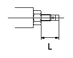
Temporary full load screw adjustment
Set the full load screw protrusion at L mm at assembly.
----------
L=14+-0.5mm
----------
L=14+-0.5mm
----------
L=14+-0.5mm
----------
L=14+-0.5mm
0000001901 STOP LEVER ADJUSTMENT
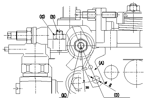
Adjustment of the stop lever
1. Confirm that the starting injection quantity is within standards at the normal position.
If below the specified lower limit, move the stop lever serrations one tooth and reconfirm.
2. Pull the stop lever (A) to the fuel cut direction at the standard idling speed of N and adjust the screw (B) to the position Q.
Fix nut (C) to the torque T at the position where the clearance between the stop lever and the end of the screw is L mm (the screw is returned 2 turns).
The head of the screw must protrude above the face of the nut. If the head of the screw is below the face of the nut, adjust the clearance between the stop lever A and the end of the screw at Q to L mm or more.
3. If adjustment in item 2 is not possible, move the stop lever installation position 1 tooth.
4. The stop lever's operating force is max. M kg (at R = 35). The stop lever must operate smoothly.
(D) Normal position
(E) Stop position
----------
N=400r/min Q=0mm3/st L=2mm T=6~9N-m(0.6~0.9kgf-m) M=4.0kg
----------
S=Dia6.5+0.09mm R=35mm
----------
N=400r/min Q=0mm3/st L=2mm T=6~9N-m(0.6~0.9kgf-m) M=4.0kg
----------
S=Dia6.5+0.09mm R=35mm
0000002001 W-CSD ADJUSTMENT
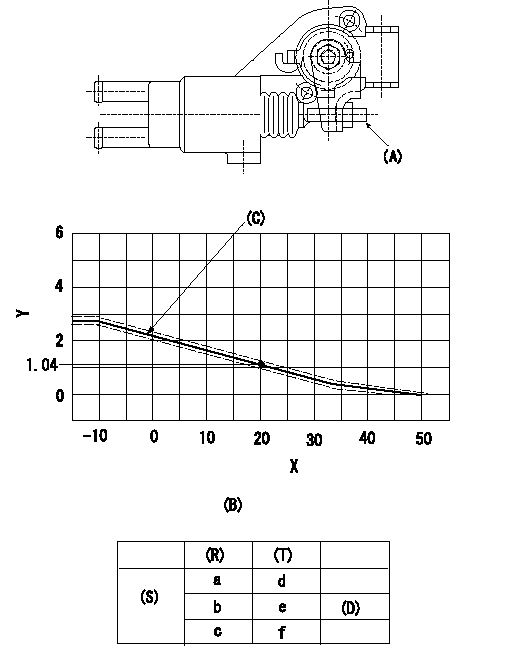
Adjustment of the W-CSD
Adjust screw A so that the timer advance angle determined in (B) can be obtained.
Y:Timer stroke TA (mm)
X:Temperature t (deg C)
(B) Timer stroke TA (mm):
TA = -0.059t + 2.22 ( -10 deg C <= t <= 20 deg C)
TA = -0.0433t + 1.906 ( 20 deg C <= t <= 35 deg C)
TA = -0.0239t + 1.227 ( 35 deg C <= t)
(C) Tolerance +-0.1(mm)
(S) Cold advance
(R) Cooling water temperature (deg C)
(T) Timer piston stroke (mm)
(D) Standard point
----------
----------
(C)=TA+-0.1mm a=56degC b=20degC c=-10degC d=0mm e=1.04+-0.4mm f=2.81+-0.6mm
----------
----------
(C)=TA+-0.1mm a=56degC b=20degC c=-10degC d=0mm e=1.04+-0.4mm f=2.81+-0.6mm
Information:
Start By:a. remove oil pump1. Check the identification marks on the connecting rods and caps as to their location in the engine. The caps must be installed in original positions in the engine.2. Turn the crankshaft until two of the pistons are at bottom center. 3. Remove connecting rod caps (1) from the connecting rods. Remove the lower half of the bearings from the caps.
Be careful not to damage the crankshaft journals. Do not turn the crankshaft while any of the connecting rod caps are removed.
4. Push the connecting rod away from the crankshaft, and remove the upper half of the bearings from the connecting rods.5. Make sure the surface of the connecting rod where the bearings make contact is clean and free of dirt.
Make sure the tabs on the bearings are in alignment with the notches in the connecting rods and caps.
6. Install the upper half of new bearings in the connecting rods.7. Pull the connecting rod down slowly on the crankshaft.
Make sure the surfaces where the bearings make contact in the caps are clean and free of dirt.
8. Install new bearings (2) in the caps. Make sure the tabs on the bearings are in alignment with the notches in the caps.The serviceman must be very careful to use Plastigage correctly. The following points must be remembered:... Make sure that the backs of the bearings and the bores are clean and dry.... Make sure that the bearing locking tabs are properly seated in their slots.... The crankshaft must be free of oil where the Plastigage touches it.... Put a piece of Plastigage on the crown of the bearing half that is in the cap. Do not allow the Plastigage to extend over the edge of the bearing.... Install the bearing cap using the correct torque-turn specifications. Do not use an impact wrench. Be careful not to dislodge the bearing when the cap is installed.... Do not turn the crankshaft with the Plastigage installed. ... Carefully remove the cap but do not remove the Plastigage. Measure the width of the Plastigage while it is in the bearing cap or on the crankshaft journal. Do this by using the correct scale on the package. Record the measurements.... Remove the Plastigage before installing the cap.When using Plastigage, the readings can sometimes be unclear. For example, all parts of the Plastigage are not the same width. Measure the major widths to make sure that they are within the specification range. Also, experience has shown that when checking clearances tighter than 0.10 mm (.004 in) the readings may be low by 0.013 to 0.025 mm (.0005 to .0010 in). Out-of-round journals can give faulty readings. Also, journal taper may be indicated when one end of the Plastigage is wider that the other.For complete details concerning measuring bearing clearances, see Engine Bearings & Crankshafts, SEBD0531.9. Put 2P-2506 Thread Lubricant on the threads of the bolts in the connecting rods.10. Check the bearing clearance with Plastigage (A) as follows:
When Plastigage is used to check
Have questions with 104742-7540?
Group cross 104742-7540 ZEXEL
Yanmar
104742-7540
INJECTION-PUMP ASSEMBLY
4JH4-TE
4JH4-TE