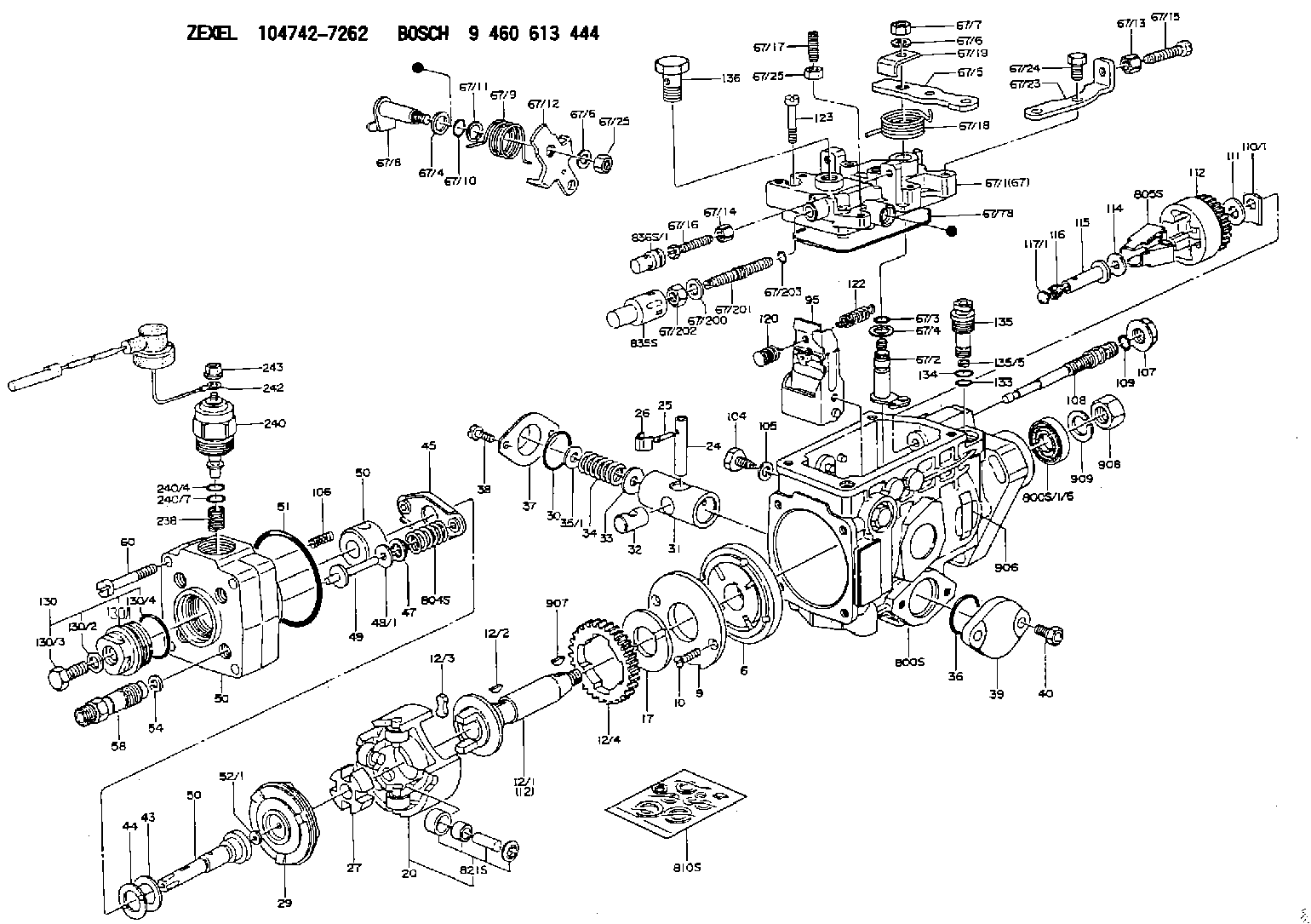
Information injection-pump assembly
BOSCH
9 460 613 444
9460613444
ZEXEL
104742-7262
1047427262
YANMAR
12969751910
12969751910

Rating:
Components :
| 0. | INJECTION-PUMP ASSEMBLY | 104742-7262 |
| 1. | _ | |
| 2. | FUEL INJECTION PUMP | 104642-7262 |
| 3. | NUMBER PLATE | 146910-6300 |
| 4. | _ | |
| 5. | CAPSULE | |
| 6. | ADJUSTING DEVICE | |
| 7. | NOZZLE AND HOLDER ASSY | |
| 8. | Nozzle and Holder | |
| 9. | Open Pre:MPa(Kqf/cm2) | 21.6{220} |
| 10. | NOZZLE-HOLDER | |
| 11. | NOZZLE |
Scheme ###:
| 1/6. | [1] | 146601-0700 | PACKING RING |
| 6. | [1] | 146100-0120 | SUPPLY PUMP |
| 9. | [1] | 146103-0000 | COVER |
| 10. | [2] | 139104-0000 | FLAT-HEAD SCREW |
| 12. | [1] | 146200-0820 | DRIVE SHAFT |
| 12/1. | [1] | 146200-0800 | DRIVE SHAFT |
| 12/2. | [1] | 146201-0000 | WOODRUFF KEY |
| 12/3. | [2] | 146202-0100 | DAMPER |
| 12/4. | [1] | 146203-0000 | TOOTHED GEAR |
| 17. | [1] | 146204-0000 | PLAIN WASHER |
| 20. | [1] | 146210-8420 | ROLLER SET |
| 24. | [1] | 146303-0400 | BEARING PIN |
| 25. | [1] | 146304-0000 | BEARING PIN |
| 26. | [1] | 146305-0000 | CLAMPING BAND |
| 27. | [1] | 146205-0300 | SLOTTED WASHER |
| 29. | [1] | 146220-5020 | CAM PLATE |
| 30. | [1] | 146600-0800 | O-RING |
| 31. | [1] | 146300-4800 | PUMP PLUNGER |
| 32. | [1] | 146301-0000 | SLIDING PIECE |
| 33. | [1] | 146603-0700 | SHIM D17.5&7.5T0.60 |
| 34. | [1] | 146302-4100 | COMPRESSION SPRING |
| 35/1. | [0] | 146603-0700 | SHIM D17.5&7.5T0.60 |
| 35/1. | [0] | 146603-0800 | SHIM D17.5&7.5T0.70 |
| 35/1. | [0] | 146603-0900 | SHIM D17.5&7.5T0.90 |
| 35/1. | [0] | 146603-1000 | SHIM D17.5&7.5T1.00 |
| 35/1. | [0] | 146603-1100 | SHIM D17.5&7.5T1.20 |
| 35/1. | [0] | 146603-3600 | SHIM D17.5&7.5T2.40 |
| 36. | [1] | 146600-0800 | O-RING |
| 37. | [1] | 146310-0700 | COVER |
| 38. | [2] | 146620-5000 | BLEEDER SCREW |
| 39. | [1] | 146310-5200 | COVER |
| 40. | [2] | 146620-5000 | BLEEDER SCREW |
| 43. | [1] | 146230-0000 | SHIM |
| 44. | [1] | 146230-0100 | PLAIN WASHER |
| 45. | [1] | 146231-0001 | SLOTTED WASHER |
| 47. | [2] | 146233-0000 | SLOTTED WASHER |
| 48/1. | [1] | 146603-0000 | SHIM D17.0&5.2T0.50 |
| 48/1. | [1] | 146603-0100 | SHIM D17.0&5.2T0.80 |
| 48/1. | [1] | 146603-0200 | SHIM D17.0&5.2T1.00 |
| 48/1. | [1] | 146603-0300 | SHIM D17.0&5.2T1.20 |
| 48/1. | [1] | 146603-0400 | SHIM D17.0&5.2T1.50 |
| 48/1. | [1] | 146603-0500 | SHIM D17.0&5.2T1.80 |
| 48/1. | [1] | 146603-0600 | SHIM D17.0&5.2T2.00 |
| 48/1. | [1] | 146690-1400 | SHIM D17&5.2T0.9 |
| 48/1. | [1] | 146690-1500 | SHIM D17&5.2T1.1 |
| 48/1. | [1] | 146690-1600 | SHIM D17&5.2T1.3 |
| 48/1. | [1] | 146690-1700 | SHIM D17&5.2T1.4 |
| 48/1. | [1] | 146690-1800 | SHIM D17&5.2T1.6 |
| 48/1. | [1] | 146690-1900 | SHIM D17&5.2T1.7 |
| 48/1. | [1] | 146690-5800 | SHIM D17&5.2T2.1 |
| 48/1. | [1] | 146690-5900 | SHIM D17&5.2T2.2 |
| 48/1. | [1] | 146690-6000 | SHIM D17&5.2T2.3 |
| 48/1. | [1] | 146690-6100 | SHIM D17&5.2T2.4 |
| 48/1. | [1] | 146690-6200 | SHIM D17&5.2T2.5 |
| 48/1. | [1] | 146690-6300 | SHIM D17&5.2T2.6 |
| 48/1. | [1] | 146690-6400 | SHIM D17&5.2T2.7 |
| 48/1. | [1] | 146690-6500 | SHIM D17&5.2T2.8 |
| 48/1. | [1] | 146690-6600 | SHIM D17&5.2T2.9 |
| 48/1. | [1] | 146690-6700 | SHIM D17&5.2T3.0 |
| 48/1. | [1] | 146690-6800 | SHIM D17&5.2T3.1 |
| 48/1. | [1] | 146690-6900 | SHIM D17&5.2T3.2 |
| 48/1. | [1] | 146690-7000 | SHIM D17&5.2T3.3 |
| 48/1. | [1] | 146690-7100 | SHIM D17&5.2T3.4 |
| 48/1. | [1] | 146690-7200 | SHIM D17&5.2T0.4 |
| 48/1. | [1] | 146690-7300 | SHIM D17&5.2T0.6 |
| 48/1. | [1] | 146690-7400 | SHIM D17&5.2T0.7 |
| 48/1. | [1] | 146690-7500 | SHIM D17&5.2T1.9 |
| 48/1. | [1] | 146690-7800 | SHIM D17&5.2T0.2 |
| 49. | [2] | 146234-0600 | GUIDE PIN |
| 50. | [1] | 146402-4620 | HYDRAULIC HEAD |
| 50. | [1] | 146402-4620 | HYDRAULIC HEAD |
| 50. | [1] | 146402-4620 | HYDRAULIC HEAD |
| 51. | [1] | 146600-0000 | O-RING |
| 52/1. | [1] | 146420-0000 | SHIM D9.5&3.0T1.90 |
| 52/1. | [1] | 146420-0100 | SHIM D9.5&3.0T1.92 |
| 52/1. | [1] | 146420-0200 | SHIM D9.5&3.0T1.94 |
| 52/1. | [1] | 146420-0300 | SHIM D9.5&3.0T1.96 |
| 52/1. | [1] | 146420-0400 | SHIM D9.5&3.0T1.98 |
| 52/1. | [1] | 146420-0500 | SHIM D9.5&3.0T2.00 |
| 52/1. | [1] | 146420-0600 | SHIM D9.5&3.0T2.02 |
| 52/1. | [1] | 146420-0700 | SHIM D9.5&3.0T2.04 |
| 52/1. | [1] | 146420-0800 | SHIM D9.5&3.0T2.06 |
| 52/1. | [1] | 146420-0900 | SHIM D9.5&3.0T2.08 |
| 52/1. | [1] | 146420-1000 | SHIM D9.5&3.0T2.10 |
| 52/1. | [1] | 146420-1100 | SHIM D9.5&3.0T2.12 |
| 52/1. | [1] | 146420-1200 | SHIM D9.5&3.0T2.14 |
| 52/1. | [1] | 146420-1300 | SHIM D9.5&3.0T2.16 |
| 52/1. | [1] | 146420-1400 | SHIM D9.5&3.0T2.18 |
| 52/1. | [1] | 146420-1500 | SHIM D9.5&3.0T2.20 |
| 52/1. | [1] | 146420-1600 | SHIM D9.5&3.0T2.22 |
| 52/1. | [1] | 146420-1700 | SHIM D9.5&3.0T2.24 |
| 52/1. | [1] | 146420-1800 | SHIM D9.5&3.0T2.26 |
| 52/1. | [1] | 146420-1900 | SHIM D9.5&3.0T2.28 |
| 52/1. | [1] | 146420-2000 | SHIM D9.5&3.0T2.30 |
| 52/1. | [1] | 146420-2100 | SHIM D9.5&3.0T2.32 |
| 52/1. | [1] | 146420-2200 | SHIM D9.5&3.0T2.34 |
| 52/1. | [1] | 146420-2300 | SHIM D9.5&3.0T2.36 |
| 52/1. | [1] | 146420-2400 | SHIM D9.5&3.0T2.38 |
| 52/1. | [1] | 146420-2500 | SHIM D9.5&3.0T2.40 |
| 52/1. | [1] | 146420-2600 | SHIM D9.5&3.0T2.42 |
| 52/1. | [1] | 146420-2700 | SHIM D9.5&3.0T2.44 |
| 52/1. | [1] | 146420-2800 | SHIM D9.5&3.0T2.46 |
| 52/1. | [1] | 146420-2900 | SHIM D9.5&3.0T2.48 |
| 52/1. | [1] | 146420-3000 | SHIM D9.5&3.0T2.50 |
| 52/1. | [1] | 146420-3100 | SHIM D9.5&3.0T2.52 |
| 52/1. | [1] | 146420-3200 | SHIM D9.5&3.0T2.54 |
| 52/1. | [1] | 146420-3300 | SHIM D9.5&3.0T2.56 |
| 52/1. | [1] | 146420-3400 | SHIM D9.5&3.0T2.58 |
| 52/1. | [1] | 146420-3500 | SHIM D9.5&3.0T2.60 |
| 52/1. | [1] | 146420-3600 | SHIM D9.5&3.0T2.62 |
| 52/1. | [1] | 146420-3700 | SHIM D9.5&3.0T2.64 |
| 52/1. | [1] | 146420-3800 | SHIM D9.5&3.0T2.66 |
| 52/1. | [1] | 146420-3900 | SHIM D9.5&3.0T2.68 |
| 52/1. | [1] | 146420-4000 | SHIM D9.5&3.0T2.70 |
| 52/1. | [1] | 146420-4100 | SHIM D9.5&3.0T2.72 |
| 52/1. | [1] | 146420-4200 | SHIM D9.5&3.0T2.74 |
| 52/1. | [1] | 146420-4300 | SHIM D9.5&3.0T2.76 |
| 52/1. | [1] | 146420-4400 | SHIM D9.5&3.0T2.78 |
| 52/1. | [1] | 146420-4500 | SHIM D9.5&3.0T2.80 |
| 52/1. | [1] | 146420-4600 | SHIM D9.5&3.0T2.82 |
| 52/1. | [1] | 146420-4700 | SHIM D9.5&3.0T2.84 |
| 52/1. | [1] | 146420-4800 | SHIM D9.5&3.0T2.86 |
| 52/1. | [1] | 146420-4900 | SHIM D9.5&3.0T2.88 |
| 52/1. | [1] | 146420-5000 | SHIM D9.5&3.0T2.90 |
| 52/1. | [1] | 146420-5100 | SHIM D9.5&3.0T1.74 |
| 52/1. | [1] | 146420-5200 | SHIM D9.5&3.0T1.76 |
| 52/1. | [1] | 146420-5300 | SHIM D9.5&3.0T1.78 |
| 52/1. | [1] | 146420-5400 | SHIM D9.5&3.0T1.80 |
| 52/1. | [1] | 146420-5500 | SHIM D9.5&3.0T1.82 |
| 52/1. | [1] | 146420-5600 | SHIM D9.5&3.0T1.84 |
| 52/1. | [1] | 146420-5700 | SHIM D9.5&3.0T1.86 |
| 52/1. | [1] | 146420-5800 | SHIM D9.5&3.0T1.88 |
| 54. | [4] | 146433-0100 | GASKET D12&6.4T1.00 |
| 58. | [4] | 146440-2520 | PRESSURE-CONTROL VALVE |
| 60. | [4] | 139106-0100 | FLAT-HEAD SCREW |
| 67. | [1] | 146821-7320 | GOVERNOR COVER |
| 67/1. | [1] | 146508-6321 | GOVERNOR COVER |
| 67/2. | [1] | 146515-0220 | CONTROL SHAFT |
| 67/3. | [1] | 146600-0100 | O-RING |
| 67/4. | [2] | 139310-0200 | PLAIN WASHER |
| 67/4. | [2] | 139310-0200 | PLAIN WASHER |
| 67/5. | [1] | 146831-7900 | CONTROL LEVER |
| 67/5B. | [1] | 146831-8000 | CONTROL LEVER |
| 67/6. | [2] | 014110-6440 | LOCKING WASHER |
| 67/6. | [2] | 014110-6440 | LOCKING WASHER |
| 67/7. | [1] | 013020-6040 | UNION NUT M6P1H5 |
| 67/8. | [1] | 146515-1120 | LEVER SHAFT |
| 67/9. | [1] | 146587-4600 | COILED SPRING |
| 67/10. | [1] | 146600-0200 | O-RING |
| 67/11. | [1] | 146602-0100 | PLAIN WASHER D14&10.1T1.50 |
| 67/12. | [1] | 146540-0000 | CONTROL LEVER |
| 67/13. | [1] | 013020-6040 | UNION NUT M6P1H5 |
| 67/14. | [1] | 146621-1700 | UNION NUT |
| 67/15. | [1] | 146526-4500 | BLEEDER SCREW |
| 67/16. | [1] | 146526-2800 | BLEEDER SCREW |
| 67/17. | [1] | 146526-0000 | FLAT-HEAD SCREW |
| 67/18. | [1] | 146587-4000 | COILED SPRING |
| 67/19. | [1] | 146541-0000 | ANGLE PIECE |
| 67/23. | [1] | 146613-1300 | BRACKET |
| 67/24. | [2] | 139006-4700 | BLEEDER SCREW |
| 67/25. | [2] | 013020-6040 | UNION NUT M6P1H5 |
| 67/25. | [2] | 013020-6040 | UNION NUT M6P1H5 |
| 67/78. | [1] | 146600-4400 | SEAL RING |
| 67/200. | [1] | 139308-0300 | PLAIN WASHER |
| 67/201. | [1] | 146545-3400 | THREADED PIN L53.00 |
| 67/201B. | [1] | 146545-3500 | THREADED PIN L55.00 |
| 67/201C. | [1] | 146545-3600 | THREADED PIN L57.00 |
| 67/202. | [1] | 139208-0900 | UNION NUT |
| 67/203. | [1] | 146600-1200 | O-RING |
| 95. | [1] | 146871-5221 | FULCRUM LEVER |
| 104. | [2] | 146568-0000 | SLOTTED SPRING PIN |
| 105. | [2] | 026508-1140 | GASKET D11.4&8.2T1 |
| 106. | [2] | 146588-0500 | COILED SPRING |
| 107. | [1] | 146569-0300 | UNION NUT |
| 108. | [1] | 146570-0100 | GOVERNOR SHAFT |
| 109. | [1] | 146600-0400 | O-RING |
| 110/1. | [1] | 146571-0000 | SHIM D20.2&8.3T1.05 |
| 110/1. | [1] | 146571-0100 | SHIM D20.2&8.3T1.25 |
| 110/1. | [1] | 146571-0200 | SHIM D20.2&8.3T1.45 |
| 110/1. | [1] | 146571-0300 | SHIM D20.2&8.3T1.65 |
| 110/1. | [1] | 146571-0400 | SHIM D20.2&8.3T1.85 |
| 110/1. | [1] | 146571-0500 | SHIM D20.2&8.3T1.15 |
| 110/1. | [1] | 146571-0600 | SHIM D20.2&8.3T1.35 |
| 110/1. | [1] | 146571-0700 | SHIM D20.2&8.3T1.55 |
| 110/1. | [1] | 146571-0800 | SHIM D20.2&8.3T1.75 |
| 111. | [1] | 146602-0600 | PLAIN WASHER D20&8.4T1.40 |
| 112. | [1] | 146572-0020 | FLYWEIGHT ASSEMBLY |
| 114. | [1] | 146602-0500 | PLAIN WASHER D17&6.4T1.60 |
| 115. | [1] | 146975-4200 | SLIDING SLEEVE |
| 116. | [1] | 146576-0200 | CAP |
| 117/1. | [1] | 146577-1800 | PLUG L2.10 |
| 117/1. | [1] | 146577-1900 | PLUG L2.30 |
| 117/1. | [1] | 146577-2000 | PLUG L2.50 |
| 117/1. | [1] | 146577-2100 | PLUG L2.70 |
| 117/1. | [1] | 146577-2200 | PLUG L2.90 |
| 117/1. | [1] | 146577-2300 | PLUG L3.10 |
| 117/1. | [1] | 146577-2400 | PLUG L3.30 |
| 117/1. | [1] | 146577-2500 | PLUG L3.50 |
| 117/1. | [1] | 146577-2600 | PLUG L3.70 |
| 117/1. | [1] | 146577-2700 | PLUG L3.90 |
| 117/1. | [1] | 146577-2800 | PLUG L4.10 |
| 117/1. | [1] | 146577-2900 | PLUG L4.30 |
| 117/1. | [1] | 146577-3000 | PLUG L4.50 |
| 117/1. | [1] | 146577-3100 | PLUG L4.70 |
| 117/1. | [1] | 146577-3200 | PLUG L4.90 |
| 117/1. | [1] | 146577-3300 | PLUG L5.10 |
| 117/1. | [1] | 146577-6700 | PLUG L2.2 |
| 117/1. | [1] | 146577-6800 | PLUG L2.4 |
| 117/1. | [1] | 146577-6900 | PLUG L2.6 |
| 117/1. | [1] | 146577-7000 | PLUG L2.8 |
| 117/1. | [1] | 146577-7100 | PLUG L3.0 |
| 117/1. | [1] | 146577-7200 | PLUG L3.2 |
| 117/1. | [1] | 146577-7300 | PLUG L3.4 |
| 117/1. | [1] | 146577-7400 | PLUG L3.6 |
| 117/1. | [1] | 146577-7500 | PLUG L3.8 |
| 117/1. | [1] | 146577-7600 | PLUG L4.0 |
| 117/1. | [1] | 146577-7700 | PLUG L4.2 |
| 117/1. | [1] | 146577-7800 | PLUG L4.4 |
| 117/1. | [1] | 146577-7900 | PLUG L4.6 |
| 117/1. | [1] | 146577-8000 | PLUG L4.8 |
| 117/1. | [1] | 146577-8100 | PLUG L5.0 |
| 117/1. | [1] | 146877-0000 | PLUG L5.2 |
| 117/1. | [1] | 146877-0100 | PLUG L5.3 |
| 117/1. | [1] | 146877-0200 | PLUG L5.4 |
| 117/1. | [1] | 146877-0300 | PLUG L5.5 |
| 117/1. | [1] | 146877-4700 | PLUG |
| 117/1. | [1] | 146877-4800 | PLUG |
| 117/1. | [1] | 146877-4900 | PLUG |
| 117/1. | [1] | 146877-5000 | PLUG |
| 120. | [1] | 146879-5620 | RETAINING PIN |
| 122. | [1] | 146580-0600 | GOVERNOR SPRING |
| 123. | [4] | 139106-0200 | FLAT-HEAD SCREW |
| 130. | [1] | 146421-1120 | CAPSULE |
| 130/1. | [1] | 146421-1100 | CAPSULE |
| 130/2. | [1] | 139508-0200 | GASKET D11.4&8.2T1 |
| 130/3. | [1] | 146422-0300 | BLEEDER SCREW |
| 130/4. | [1] | 146600-0500 | O-RING |
| 133. | [1] | 146600-0600 | O-RING |
| 134. | [1] | 146600-0700 | O-RING |
| 135. | [1] | 146110-0220 | CONTROL VALVE |
| 135/5. | [1] | 146114-0000 | SPRING WASHER |
| 136. | [1] | 146120-2620 | OVER FLOW VALVE |
| 238. | [1] | 146655-0400 | COILED SPRING |
| 240. | [1] | 146650-4520 | PULLING ELECTROMAGNET |
| 240/4. | [1] | 146600-1700 | O-RING |
| 240/7. | [1] | 146600-1700 | O-RING |
| 242. | [1] | 146658-4820 | WIRE |
| 243. | [1] | 146621-4901 | UNION NUT |
| 800S. | [1] | 146018-9820 | PUMP HOUSING |
| 800S/1/6. | [1] | 146601-0700 | PACKING RING |
| 804S. | [1] | 146232-0720 | COMPRESSION SPRING |
| 805S. | [1] | 146574-0720 | PARTS SET |
| 810S. | [1] | 146600-1120 | REPAIR SET |
| 821S. | [1] | 146210-5820 | ROLLER SET |
| 835S. | [1] | 146598-1000 | CAP |
| 836S/1. | [1] | 146598-0600 | CAP L18 |
| 836S/1. | [1] | 146598-0700 | CAP L21 |
| 836S/1. | [1] | 146598-0800 | CAP L24 |
| 836S/1. | [1] | 146598-0900 | CAP L27 |
| 906. | [1] | 146910-6300 | NAMEPLATE |
| 907. | [1] | 029470-4030 | WOODRUFF KEY |
| 908. | [1] | 013121-4140 | UNION NUT M14P1.5H11 |
| 909. | [1] | 029321-4050 | LOCKING WASHER |
Include in #2:
104742-7262
as INJECTION-PUMP ASSEMBLY
Cross reference number
BOSCH
9 460 613 444
9460613444
ZEXEL
104742-7262
1047427262
YANMAR
12969751910
12969751910
Zexel num
Bosch num
Firm num
Name
9 460 613 444
12969751910 YANMAR
INJECTION-PUMP ASSEMBLY
4JH3 * K 11CJ VE4 VE
4JH3 * K 11CJ VE4 VE
Calibration Data:
Adjustment conditions
Test oil
1404 Test oil ISO4113orSAEJ967d
1404 Test oil ISO4113orSAEJ967d
Test oil temperature
degC
45
45
50
Nozzle
105780-0060
Bosch type code
NP-DN0SD1510
Nozzle holder
105780-2150
Opening pressure
MPa
13
13
13.3
Opening pressure
kgf/cm2
133
133
136
Injection pipe
157805-7320
Injection pipe
Inside diameter - outside diameter - length (mm) mm 2-6-450
Inside diameter - outside diameter - length (mm) mm 2-6-450
Joint assembly
157641-4720
Tube assembly
157641-4020
Transfer pump pressure
kPa
20
20
20
Transfer pump pressure
kgf/cm2
0.2
0.2
0.2
Direction of rotation (viewed from drive side)
Right R
Right R
Injection timing adjustment
Pump speed
r/min
1925
1925
1925
Average injection quantity
mm3/st.
63.6
63.1
64.1
Difference in delivery
mm3/st.
5.5
Basic
*
Oil temperature
degC
50
48
52
Injection timing adjustment_02
Pump speed
r/min
500
500
500
Average injection quantity
mm3/st.
40.9
32.9
48.9
Oil temperature
degC
48
46
50
Injection timing adjustment_03
Pump speed
r/min
900
900
900
Average injection quantity
mm3/st.
44.2
37.2
51.2
Oil temperature
degC
50
48
52
Injection timing adjustment_04
Pump speed
r/min
1350
1350
1350
Average injection quantity
mm3/st.
58.7
51.7
65.7
Oil temperature
degC
50
48
52
Injection timing adjustment_05
Pump speed
r/min
1925
1925
1925
Average injection quantity
mm3/st.
63.6
62.6
64.6
Difference in delivery
mm3/st.
6
Basic
*
Oil temperature
degC
50
48
52
Injection quantity adjustment
Pump speed
r/min
2175
2175
2175
Average injection quantity
mm3/st.
5.2
2.2
8.2
Difference in delivery
mm3/st.
3
Basic
*
Oil temperature
degC
52
50
54
Injection quantity adjustment_02
Pump speed
r/min
2300
2300
2300
Average injection quantity
mm3/st.
3
Oil temperature
degC
52
50
54
Injection quantity adjustment_03
Pump speed
r/min
2175
2175
2175
Average injection quantity
mm3/st.
5.2
0.7
9.7
Difference in delivery
mm3/st.
3
Basic
*
Oil temperature
degC
52
50
54
Governor adjustment
Pump speed
r/min
338
338
338
Average injection quantity
mm3/st.
15
13
17
Difference in delivery
mm3/st.
3
Basic
*
Oil temperature
degC
48
46
50
Governor adjustment_02
Pump speed
r/min
338
338
338
Average injection quantity
mm3/st.
15
12.5
17.5
Difference in delivery
mm3/st.
3
Basic
*
Oil temperature
degC
48
46
50
Timer adjustment
Pump speed
r/min
100
100
100
Average injection quantity
mm3/st.
85
65
105
Basic
*
Oil temperature
degC
48
46
50
Remarks
Full
Full
Timer adjustment_02
Pump speed
r/min
150
150
150
Average injection quantity
mm3/st.
85
65
105
Basic
*
Oil temperature
degC
48
46
50
Remarks
Full
Full
Timer adjustment_03
Pump speed
r/min
100
100
100
Average injection quantity
mm3/st.
85
65
105
Oil temperature
degC
48
46
50
Remarks
Full
Full
Speed control lever angle
Pump speed
r/min
100
100
100
Average injection quantity
mm3/st.
0
0
0
Oil temperature
degC
48
46
50
Remarks
Magnet ON at idling position and reversed operate
Magnet ON at idling position and reversed operate
Speed control lever angle_02
Pump speed
r/min
338
338
338
Average injection quantity
mm3/st.
0
0
0
Oil temperature
degC
48
46
50
Remarks
Magnet ON at idling position and reversed operate
Magnet ON at idling position and reversed operate
Speed control lever angle_03
Pump speed
r/min
100
100
100
Average injection quantity
mm3/st.
0
0
0
Oil temperature
degC
48
46
50
Remarks
Magnet OFF at idling position and stop lever operate
Magnet OFF at idling position and stop lever operate
Speed control lever angle_04
Pump speed
r/min
338
338
338
Average injection quantity
mm3/st.
0
0
0
Oil temperature
degC
48
46
50
Remarks
Magnet OFF at idling position and stop lever operate
Magnet OFF at idling position and stop lever operate
0000000901
Pump speed
r/min
1050
1050
1050
Overflow quantity
cm3/min
1280
1050
1510
Oil temperature
degC
50
48
52
Stop lever angle
Pump speed
r/min
1050
1050
1050
Pressure
kPa
510
481
539
Pressure
kgf/cm2
5.2
4.9
5.5
Basic
*
Oil temperature
degC
50
48
52
Stop lever angle_02
Pump speed
r/min
950
950
950
Pressure
kPa
490
451
529
Pressure
kgf/cm2
5
4.6
5.4
Oil temperature
degC
50
48
52
Stop lever angle_03
Pump speed
r/min
1050
1050
1050
Pressure
kPa
510
471
549
Pressure
kgf/cm2
5.2
4.8
5.6
Basic
*
Oil temperature
degC
50
48
52
Stop lever angle_04
Pump speed
r/min
1925
1925
1925
Pressure
kPa
696
647
745
Pressure
kgf/cm2
7.1
6.6
7.6
Oil temperature
degC
50
48
52
0000001101
Pump speed
r/min
1050
1050
1050
Timer stroke
mm
0.8
0.6
1
Basic
*
Oil temperature
degC
50
48
52
_02
Pump speed
r/min
1050
1050
1050
Timer stroke
mm
0.8
0.4
1.2
Basic
*
Oil temperature
degC
50
48
52
_03
Pump speed
r/min
1925
1925
1925
Timer stroke
mm
1.7
1.2
2.1
Oil temperature
degC
50
48
52
0000001201
Max. applied voltage
V
8
8
8
Test voltage
Reverse operation (At Normal: OFF, At Stop: ON) V 13 12 14
Reverse operation (At Normal: OFF, At Stop: ON) V 13 12 14
Timing setting
K dimension
mm
3.6
3.5
3.7
KF dimension
mm
5.54
5.44
5.64
MS dimension
mm
0.9
0.8
1
Pre-stroke
mm
0.2
0.18
0.22
Control lever angle alpha
deg.
25
21
29
Control lever angle beta
deg.
39.5
34.5
44.5
Test data Ex:
0000001801 Temp. adjust full-load screw
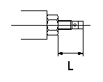
Temporary full load screw adjustment
Set the full load screw protrusion at L mm at assembly.
----------
L=14+-0.5mm
----------
L=14+-0.5mm
----------
L=14+-0.5mm
----------
L=14+-0.5mm
0000001901 STOP LEVER ADJUSTMENT
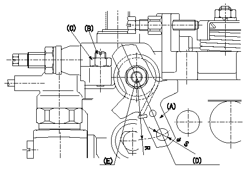
Adjustment of the stop lever
1. Confirm that the starting injection quantity is within standards at the normal position.
If below the specified lower limit, move the stop lever serrations one tooth and reconfirm.
2. Pull the stop lever (A) to the fuel cut direction at the standard idling speed of N and adjust the screw (B) to the position Q.
Fix nut (C) to the torque T at the position where the clearance between the stop lever and the end of the screw is L mm (the screw is returned 2 turns).
The head of the screw must protrude above the face of the nut. If the head of the screw is below the face of the nut, adjust the clearance between the stop lever A and the end of the screw at Q to L mm or more.
3. If adjustment in item 2 is not possible, move the stop lever installation position 1 tooth.
4. The stop lever's operating force is max. M kg (at R = 35). The stop lever must operate smoothly.
(D) Normal position
(E) Stop position
----------
N=338r/min Q=0mm3/st T=6~9N-m(0.6~0.9kgf-m) L=2mm M=4.0kg
----------
S=Dia6.5+0.09mm R=35mm
----------
N=338r/min Q=0mm3/st T=6~9N-m(0.6~0.9kgf-m) L=2mm M=4.0kg
----------
S=Dia6.5+0.09mm R=35mm
Information:
Figure 1The next chart shows maximum acceptable voltage loss in the high current battery circuit feeding the starting motor. These values are maximums for machines of approximately 2000 SMH and up. Newer machines would be less than those shown.
Figure 2Voltages greater than those shown are most often caused by loose and/or corroded connections or defective switch contacts.Diagnosis Procedure
Do not operate the starting motor for more than 30 seconds at a time. After 30 seconds, the cranking must be stopped for two minutes to allow the starting motor to cool. This will prevent damage to the starting motor due to excessive heat buildup.
If the starting motor cranks real slow or does not crank at all, do the following procedure:1. Measure battery voltage at the battery posts with the multimeter while cranking or attempting to crank the engine. Make sure to measure the battery posts. Do not measure the cable post clamps.2. Is battery voltage equal to or greater than shown in Figure 1? a. If the battery voltage is OK, go to Step 3.b. If the battery voltage is too low, test the battery as shown in Special Instruction Form No. SEHS7633. A low battery can be caused by battery condition or a shorted starting motor.3. Measure current draw on the (+) battery cable between the battery and the starting motor solenoid with the clamp-on ammeter. The maximum current draw allowed is shown in Specifications under Load Test. The figures shown in Specifications are taken at temperature of 27°C (80°F). At temperatures below 27°C (80°F), the voltage will be less and the current draw will be higher. If current draw is too much, the starting motor has a problem and must be removed for repair or replacement. If voltage at the battery post is within approximately 2 volts of the lowest value in the applicable temperature range of Figure 1 and if the large starting motor cables get hot, then the starting motor has a problem and the 8T0900 Ammeter test is not needed.4. Measure starting motor voltage from test point (4) to (5) with the multimeter while cranking or attempting to crank the engine.5. Is voltage equal to or greater than shown in Figure 1? a. If the starting motor voltage is OK, the battery and starting motor cables down to the motor are within specifications. Go to Step 8.b. If the starting motor voltage is low, the voltage drop between the battery and the starting motor is too great. Go to Step 6.6. Measure the voltage drops in the cranking circuits with the multimeter. Compare the results with maximum voltage drops allowed in Figure 2.7. Are all the voltages within specifications? a. If the voltage drops are OK, go to Step 8, to check the engine.b. If the voltage drops are too high, repair and/or replace the faulty electrical component.8. Rotate the crankshaft by hand to make sure it is not locked up. Check oil viscosity and any external loads that would affect engine rotation.9. Is the