Information injection-pump assembly
BOSCH
9 460 614 494
9460614494
ZEXEL
104742-7090
1047427090
YANMAR
12990151500
12990151500
Rating:
Cross reference number
BOSCH
9 460 614 494
9460614494
ZEXEL
104742-7090
1047427090
YANMAR
12990151500
12990151500
Zexel num
Bosch num
Firm num
Name
104742-7090
9 460 614 494
12990151500 YANMAR
INJECTION-PUMP ASSEMBLY
4TNE94 * K
4TNE94 * K
Calibration Data:
Adjustment conditions
Test oil
1404 Test oil ISO4113orSAEJ967d
1404 Test oil ISO4113orSAEJ967d
Test oil temperature
degC
45
45
50
Nozzle
105780-0060
Bosch type code
NP-DN0SD1510
Nozzle holder
105780-2150
Opening pressure
MPa
13
13
13.3
Opening pressure
kgf/cm2
133
133
136
Injection pipe
157805-7320
Injection pipe
Inside diameter - outside diameter - length (mm) mm 2-6-450
Inside diameter - outside diameter - length (mm) mm 2-6-450
Joint assembly
157641-4720
Tube assembly
157641-4020
Transfer pump pressure
kPa
20
20
20
Transfer pump pressure
kgf/cm2
0.2
0.2
0.2
Direction of rotation (viewed from drive side)
Right R
Right R
Injection timing adjustment
Pump speed
r/min
900
900
900
Average injection quantity
mm3/st.
57.8
57.3
58.3
Difference in delivery
mm3/st.
4.5
Basic
*
Oil temperature
degC
50
48
52
Injection timing adjustment_02
Pump speed
r/min
500
500
500
Average injection quantity
mm3/st.
47.1
47.1
47.1
Oil temperature
degC
48
46
50
Injection timing adjustment_03
Pump speed
r/min
900
900
900
Average injection quantity
mm3/st.
57.8
56.8
58.8
Difference in delivery
mm3/st.
4.5
Basic
*
Oil temperature
degC
50
48
52
Injection timing adjustment_04
Pump speed
r/min
1225
1225
1225
Average injection quantity
mm3/st.
57.3
57.3
57.3
Oil temperature
degC
50
48
52
Injection quantity adjustment
Pump speed
r/min
1350
1350
1350
Average injection quantity
mm3/st.
40.3
35.8
44.8
Difference in delivery
mm3/st.
5.5
Basic
*
Oil temperature
degC
50
48
52
Injection quantity adjustment_02
Pump speed
r/min
1350
1350
1350
Average injection quantity
mm3/st.
40.3
35.3
45.3
Difference in delivery
mm3/st.
5.5
Basic
*
Oil temperature
degC
50
48
52
Injection quantity adjustment_03
Pump speed
r/min
1500
1500
1500
Average injection quantity
mm3/st.
5
Oil temperature
degC
50
48
52
Governor adjustment
Pump speed
r/min
345
345
345
Average injection quantity
mm3/st.
23.2
21.2
25.2
Difference in delivery
mm3/st.
2
Basic
*
Oil temperature
degC
48
46
50
Governor adjustment_02
Pump speed
r/min
345
345
345
Average injection quantity
mm3/st.
23.2
20.7
25.7
Difference in delivery
mm3/st.
2
Basic
*
Oil temperature
degC
48
46
50
Timer adjustment
Pump speed
r/min
100
100
100
Average injection quantity
mm3/st.
69
64
74
Basic
*
Oil temperature
degC
48
46
50
Timer adjustment_02
Pump speed
r/min
100
100
100
Average injection quantity
mm3/st.
69
64
74
Basic
*
Oil temperature
degC
48
46
50
Speed control lever angle
Pump speed
r/min
345
345
345
Average injection quantity
mm3/st.
0
0
0
Oil temperature
degC
48
46
50
Remarks
Magnet OFF
Magnet OFF
0000000901
Pump speed
r/min
1000
1000
1000
Overflow quantity
cm3/min
410
280
540
Oil temperature
degC
50
48
52
Stop lever angle
Pump speed
r/min
1000
1000
1000
Pressure
kPa
490
461
519
Pressure
kgf/cm2
5
4.7
5.3
Basic
*
Oil temperature
degC
50
48
52
Stop lever angle_02
Pump speed
r/min
1000
1000
1000
Pressure
kPa
490
451
529
Pressure
kgf/cm2
5
4.6
5.4
Basic
*
Oil temperature
degC
50
48
52
Stop lever angle_03
Pump speed
r/min
1200
1200
1200
Pressure
kPa
539
500
578
Pressure
kgf/cm2
5.5
5.1
5.9
Oil temperature
degC
50
48
52
0000001101
Pump speed
r/min
1000
1000
1000
Timer stroke
mm
1.6
1.4
1.8
Basic
*
Oil temperature
degC
50
48
52
_02
Pump speed
r/min
1000
1000
1000
Timer stroke
mm
1.6
1.2
2
Basic
*
Oil temperature
degC
50
48
52
_03
Pump speed
r/min
1200
1200
1200
Timer stroke
mm
2.7
2.1
3.3
Oil temperature
degC
50
48
52
0000001201
Max. applied voltage
V
16
16
16
Test voltage
V
25
24
26
Timing setting
K dimension
mm
3.1
3
3.2
KF dimension
mm
5.3
5.2
5.4
MS dimension
mm
2
1.9
2.1
Control lever angle alpha
deg.
16
12
20
Control lever angle beta
deg.
35
30
40
Test data Ex:
0000001801 STOP LEVER ADJUSTMENT
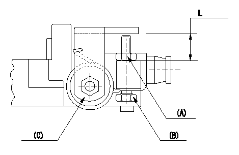
Adjustment of the stop lever
Adjust adjusting bolt (B) so that the starting injection quantity is within the standard.
Fix using nut.
(A) Adjusting nut
(C) Starting injection quantity adjusting lever
----------
----------
L=15.0~18.5mm
----------
----------
L=15.0~18.5mm
Information:
1. Remove tachometer drive (3) from transfer pump cover (4).2. Remove bolts (1). Separate cover (4) and pump body (2). 3. Remove lip-type seal (6) from the cover. Remove plug (5), the seal, spring and plunger (bypass valve) from the cover. 4. Remove nut (10) from shaft (7). Remove gear (9) and key (11).5. Remove shaft (7) and gear (8) as a unit. Remove gear (8) from drive shaft (7) with a press.6. Remove idler gear (12). 7. Remove bushing (14), two lip-type seals and the bottom bearing from pump body (2).8. Remove check valve (13).Assemble Fuel Transfer Pump
1. Install bushing (4) in body (3) with Tooling (B). The bushing must be .80 .50 mm (.031 .020 in) below the (gear) surface of the body.2. Install the check valve in the body with Tooling (A).3. Install lip-type seal (5) with Tooling (C). Install the seal until it is 26.19 .13 mm (1.031 .005 in) from the bottom (drive gear) surface of body (3) and with the lip toward bushing (4) as shown.4. Install lip-type seal (6) with Tooling (D). Install the seal until it is 14.2 0.5 mm (.559 .020 in) from the bottom (drive gear) surface of body (3) and with the lip away from seal (5) as shown.5. Install bearing (7) in body (3) with Tooling (E). The bearing must be even with the bottom (drive gear) surface of the pump body. 6. Heat gear (8) to a maximum temperature of 315° C (600° F). Install gear (8) on shaft (11) until dimension (X) is 49.71 0.25 mm (1.957 .010 in).7. Install the drive shaft and gear in body (3). Install the key, gear (10) and nut (9). Tighten the nut to a torque of 30 7 N m (22 5 lb ft).8. Install idler gear (12) in body (3).9. Install lip-type seal (2) with Tooling (C). Install the seal until it is 22.61 .05 mm (.890 .002 in) from the top surface of cover (1) with the lip toward the inside as shown. 10. Install plunger (14) (bypass valve), spring (15) and seal and plug (13) in pump cover (1). Tighten plug (13) to a torque of 37 4 N m (27 3 lb ft).
Do not let the liquid gasket enter the pump during application or assembly.
11. Put 7M-7260 Liquid Gasket Material on the surface of cover (1). Install cover (1) on pump body (3). The drive shaft must turn freely after the bolts that hold the transfer pump together are tightened.12. Install the tachometer drive on cover (1).End By:a. install fuel transfer pump
Have questions with 104742-7090?
Group cross 104742-7090 ZEXEL
Yanmar
Komatsu
Komatsu
Komatsu
Yanmar
Yanmar
Yanmar
104742-7090
9 460 614 494
12990151500
INJECTION-PUMP ASSEMBLY
4TNE94
4TNE94