Information injection-pump assembly
BOSCH
9 460 614 493
9460614493
ZEXEL
104742-7061
1047427061
KOMATSU
6202721330
6202721330
Rating:
Cross reference number
BOSCH
9 460 614 493
9460614493
ZEXEL
104742-7061
1047427061
KOMATSU
6202721330
6202721330
Zexel num
Bosch num
Firm num
Name
104742-7061
9 460 614 493
6202721330 KOMATSU
INJECTION-PUMP ASSEMBLY
4D95S-W K
4D95S-W K
Calibration Data:
Adjustment conditions
Test oil
1404 Test oil ISO4113orSAEJ967d
1404 Test oil ISO4113orSAEJ967d
Test oil temperature
degC
45
45
50
Nozzle
105780-0060
Bosch type code
NP-DN0SD1510
Nozzle holder
105780-2150
Opening pressure
MPa
13
13
13.3
Opening pressure
kgf/cm2
133
133
136
Injection pipe
157805-7320
Injection pipe
Inside diameter - outside diameter - length (mm) mm 2-6-450
Inside diameter - outside diameter - length (mm) mm 2-6-450
Joint assembly
157641-4720
Tube assembly
157641-4020
Transfer pump pressure
kPa
20
20
20
Transfer pump pressure
kgf/cm2
0.2
0.2
0.2
Direction of rotation (viewed from drive side)
Right R
Right R
Timer measuring device installation position
High pressure side HIGH PRESSURE SIDE
High pressure side HIGH PRESSURE SIDE
Injection timing adjustment
Pump speed
r/min
900
900
900
Average injection quantity
mm3/st.
47.3
46.8
47.8
Difference in delivery
mm3/st.
3
Basic
*
Oil temperature
degC
50
48
52
Injection timing adjustment_02
Pump speed
r/min
500
500
500
Average injection quantity
mm3/st.
43.9
41.4
46.4
Oil temperature
degC
48
46
50
Injection timing adjustment_03
Pump speed
r/min
900
900
900
Average injection quantity
mm3/st.
47.3
46.3
48.3
Difference in delivery
mm3/st.
3
Basic
*
Oil temperature
degC
50
48
52
Injection timing adjustment_04
Pump speed
r/min
1225
1225
1225
Average injection quantity
mm3/st.
48.8
46.3
51.3
Oil temperature
degC
50
48
52
Injection quantity adjustment
Pump speed
r/min
1350
1350
1350
Average injection quantity
mm3/st.
26.7
23.7
29.7
Difference in delivery
mm3/st.
4.5
Basic
*
Oil temperature
degC
50
48
52
Injection quantity adjustment_02
Pump speed
r/min
1350
1350
1350
Average injection quantity
mm3/st.
26.7
23.2
30.2
Difference in delivery
mm3/st.
4.5
Basic
*
Oil temperature
degC
50
48
52
Injection quantity adjustment_03
Pump speed
r/min
1500
1500
1500
Average injection quantity
mm3/st.
3
Oil temperature
degC
50
48
52
Governor adjustment
Pump speed
r/min
375
375
375
Average injection quantity
mm3/st.
11.2
9.2
13.2
Difference in delivery
mm3/st.
2
Basic
*
Oil temperature
degC
48
46
50
Governor adjustment_02
Pump speed
r/min
375
375
375
Average injection quantity
mm3/st.
11.2
8.7
13.7
Difference in delivery
mm3/st.
2
Basic
*
Oil temperature
degC
48
46
50
Timer adjustment
Pump speed
r/min
100
100
100
Average injection quantity
mm3/st.
58
53
63
Basic
*
Oil temperature
degC
48
46
50
Remarks
Full
Full
Timer adjustment_02
Pump speed
r/min
100
100
100
Average injection quantity
mm3/st.
58
53
63
Oil temperature
degC
48
46
50
Speed control lever angle
Pump speed
r/min
375
375
375
Average injection quantity
mm3/st.
0
0
0
Oil temperature
degC
48
46
50
Remarks
Magnet OFF
Magnet OFF
0000000901
Pump speed
r/min
900
900
900
Overflow quantity
cm3/min
460
330
590
Oil temperature
degC
50
48
52
Stop lever angle
Pump speed
r/min
900
900
900
Pressure
kPa
500
480
520
Pressure
kgf/cm2
5.1
4.9
5.3
Basic
*
Oil temperature
degC
50
48
52
Stop lever angle_02
Pump speed
r/min
900
900
900
Pressure
kPa
500
471
529
Pressure
kgf/cm2
5.1
4.8
5.4
Basic
*
Oil temperature
degC
50
48
52
Stop lever angle_03
Pump speed
r/min
1225
1225
1225
Pressure
kPa
579
540
618
Pressure
kgf/cm2
5.9
5.5
6.3
Oil temperature
degC
50
48
52
0000001101
Pump speed
r/min
900
900
900
Timer stroke
mm
4.8
4.6
5
Basic
*
Oil temperature
degC
50
48
52
_02
Pump speed
r/min
900
900
900
Timer stroke
mm
4.8
4.5
5.1
Basic
*
Oil temperature
degC
50
48
52
_03
Pump speed
r/min
1225
1225
1225
Timer stroke
mm
6.7
6.3
7.2
Oil temperature
degC
50
48
52
0000001201
Max. applied voltage
V
16
16
16
Test voltage
V
25
24
26
0000001401
Pump speed
r/min
900
900
900
Average injection quantity
mm3/st.
31
30.5
31.5
Timer stroke TA
mm
4
3.8
4.2
Timer stroke variation dT
mm
0.8
0.8
0.8
Basic
*
Oil temperature
degC
50
48
52
_02
Pump speed
r/min
900
900
900
Average injection quantity
mm3/st.
31
30
32
Timer stroke TA
mm
4
3.7
4.3
Basic
*
Oil temperature
degC
50
48
52
_03
Pump speed
r/min
900
900
900
Average injection quantity
mm3/st.
22
20.5
23.5
Timer stroke TA
mm
3.2
2.7
3.7
Oil temperature
degC
50
48
52
Timing setting
K dimension
mm
3.1
3
3.2
KF dimension
mm
5
4.9
5.1
MS dimension
mm
0.9
0.8
1
Control lever angle alpha
deg.
16
12
20
Control lever angle beta
deg.
38
33
43
Test data Ex:
0000001801 STARTING I/Q ADJUSTMENT
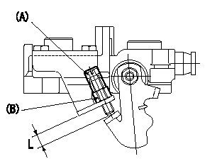
Starting Q decrease lever adjustment
At injection quantity adjustment, adjust using the bolt so that the starting injection quantity is as specified. Fix using the nut. (Tightening torque T)
Bolt (A) protrusion: L
(B) = nut
----------
L=7.4~11.1mm T=6~9N-m(0.6~0.9kgf-m)
----------
L=7.4~11.1mm
----------
L=7.4~11.1mm T=6~9N-m(0.6~0.9kgf-m)
----------
L=7.4~11.1mm
Information:
Start By:a. remove flywheelb. remove crankshaft rear seal and wear sleeve **Remove the crankshaft rear seal and wear sleeve only if the engine is equipped with the later design seal. The later design seal can be identified by the rotation marks on the seal.
Some flywheel housings will have more bolts holding the flywheel housing to the cylinder block.
1. If the engine is equipped with an electric starting motor, remove the electric starting motor from the flywheel housing.2. Remove the bolts that hold the oil pan plate to the flywheel housing. Loosen the bolts that hold the oil pan plate to the cylinder block.3. Install spacers between the oil pan plate and the cylinder block to hold the oil pan plate away from the flywheel housing.
3306 Engine Shown4. On 3306 Engines, remove turbocharger oil drain pipe (1).5. Install Tool (A) on the flywheel housing as shown, and fasten a hoist to it.6. Remove all bolts (2) and the flywheel housing from the engine. The weight of the flywheel housing is 37 kg (82 lb).Install Flywheel Housing
3306 Engine Shown1. Install Tool (A) on the flywheel housing. Fasten a hoist to the flywheel housing. 2. Put the gasket and flywheel housing in position on the engine. Install bolts (2) that hold it. Tighten the bolts to a torque of 100 14 N m (74 10 lb ft) as shown.3. Remove Tool (A) from the flywheel housing.4. On 3306 Engines, install turbocharger oil drain line (1).5. Cut the bottom of the flywheel housing gasket off even with the cylinder block and flywheel housing. Put 3S6252 RTV Silicone Adhesive/Sealant on the bottom of the gasket where it makes contact with the oil pan plate gasket.6. Remove the spacers from between the oil pan plate and the cylinder block. Install the bolts that hold the oil pan plate to the flywheel housing. Tighten the bolts that hold the oil pan plate to the cylinder block.7. If the engine is equipped with an electric starting motor, install it on the flywheel housing.End By:a. install crankshaft rear seal and wear sleeveb. install flywheel
Have questions with 104742-7061?
Group cross 104742-7061 ZEXEL
Yanmar
Komatsu
Komatsu
Komatsu
104742-7061
9 460 614 493
6202721330
INJECTION-PUMP ASSEMBLY
4D95S-W
4D95S-W