Information injection-pump assembly
ZEXEL
104742-4081
1047424081
NISSAN-DIESEL
1670031T01
1670031t01
Rating:
Cross reference number
ZEXEL
104742-4081
1047424081
NISSAN-DIESEL
1670031T01
1670031t01
Zexel num
Bosch num
Firm num
Name
Calibration Data:
Adjustment conditions
Test oil
1404 Test oil ISO4113orSAEJ967d
1404 Test oil ISO4113orSAEJ967d
Test oil temperature
degC
45
45
50
Nozzle
105780-0060
Bosch type code
NP-DN0SD1510
Nozzle holder
105780-2150
Opening pressure
MPa
13
13
13.3
Opening pressure
kgf/cm2
133
133
136
Injection pipe
157805-7320
Injection pipe
Inside diameter - outside diameter - length (mm) mm 2-6-450
Inside diameter - outside diameter - length (mm) mm 2-6-450
Joint assembly
157641-4720
Tube assembly
157641-4020
Transfer pump pressure
kPa
20
20
20
Transfer pump pressure
kgf/cm2
0.2
0.2
0.2
Direction of rotation (viewed from drive side)
Right R
Right R
Injection timing adjustment
Pump speed
r/min
1000
1000
1000
Average injection quantity
mm3/st.
60.4
59.9
60.9
Difference in delivery
mm3/st.
5
Basic
*
Injection timing adjustment_02
Pump speed
r/min
2000
2000
2000
Average injection quantity
mm3/st.
20.4
16.9
23.9
Injection timing adjustment_03
Pump speed
r/min
1750
1750
1750
Average injection quantity
mm3/st.
64.5
61.5
67.5
Injection timing adjustment_04
Pump speed
r/min
1000
1000
1000
Average injection quantity
mm3/st.
60.4
59.4
61.4
Injection timing adjustment_05
Pump speed
r/min
700
700
700
Average injection quantity
mm3/st.
54.2
51.7
56.7
Injection timing adjustment_06
Pump speed
r/min
500
500
500
Average injection quantity
mm3/st.
63.7
57.2
70.2
Injection quantity adjustment
Pump speed
r/min
2000
2000
2000
Average injection quantity
mm3/st.
20.4
17.4
23.4
Difference in delivery
mm3/st.
6
Basic
*
Injection quantity adjustment_02
Pump speed
r/min
2200
2200
2200
Average injection quantity
mm3/st.
5
Governor adjustment
Pump speed
r/min
325
325
325
Average injection quantity
mm3/st.
12.9
9.9
15.9
Difference in delivery
mm3/st.
2.5
Basic
*
Governor adjustment_02
Pump speed
r/min
325
325
325
Average injection quantity
mm3/st.
12.9
9.9
15.9
Governor adjustment_03
Pump speed
r/min
500
500
500
Average injection quantity
mm3/st.
3
Timer adjustment
Pump speed
r/min
100
100
100
Average injection quantity
mm3/st.
105
85
125
Basic
*
Speed control lever angle
Pump speed
r/min
325
325
325
Average injection quantity
mm3/st.
0
0
0
Remarks
Magnet OFF
Magnet OFF
Speed control lever angle_02
Pump speed
r/min
100
100
100
Average injection quantity
mm3/st.
0
0
0
Remarks
Magnet OFF
Magnet OFF
0000000901
Pump speed
r/min
1400
1400
1400
Overflow quantity
cm3/min
450
318
582
Stop lever angle
Pump speed
r/min
1400
1400
1400
Pressure
kPa
617.5
598
637
Pressure
kgf/cm2
6.3
6.1
6.5
Basic
*
Stop lever angle_02
Pump speed
r/min
1400
1400
1400
Pressure
kPa
617.5
598
637
Pressure
kgf/cm2
6.3
6.1
6.5
Stop lever angle_03
Pump speed
r/min
1750
1750
1750
Pressure
kPa
745.5
716
775
Pressure
kgf/cm2
7.6
7.3
7.9
0000001101
Pump speed
r/min
1500
1500
1500
Timer stroke
mm
3.7
3.5
3.9
Basic
*
_02
Pump speed
r/min
1250
1250
1250
Timer stroke
mm
1.9
1.4
2.4
_03
Pump speed
r/min
1500
1500
1500
Timer stroke
mm
3.7
3.4
4
_04
Pump speed
r/min
1750
1750
1750
Timer stroke
mm
5.6
5
6.2
_05
Pump speed
r/min
2000
2000
2000
Timer stroke
mm
7.3
6.8
7.8
0000001201
Max. applied voltage
V
16
16
16
Test voltage
V
25
24
26
Timing setting
K dimension
mm
3.1
3.1
3.1
KF dimension
mm
5.8
5.7
5.9
MS dimension
mm
0.7
0.6
0.8
Pre-stroke
mm
0.3
0.28
0.32
Control lever angle alpha
deg.
25
21
29
Control lever angle beta
deg.
36
31
41
Test data Ex:
0000001801 TEMP. ADJUST FULL-LOAD SCREW
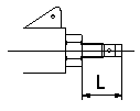
Temporary full load screw adjustment
Set the full load screw protrusion at L mm at assembly.
----------
L=14.0+-0.5mm
----------
L=14.0+-0.5mm
----------
L=14.0+-0.5mm
----------
L=14.0+-0.5mm
Information:
Start By:a. remove timing gear coverb. remove flywheel housing*c. remove engine oil cooler**d. remove oil filter base***Put the engine in time before the flywheel housing is removed. See the topic, "Finding Top Center Compression Position For No. 1 Piston" in Testing & Adjusting Manual SENR6471.**These operations must be done to install Tool (A) on the engine.
Typical Example1. Fasten the engine on Tool (A). The weight of the engine is 1362 kg (3000 lb).2. Remove the bolts and nuts that hold air cleaner group (1), pipe assembly (3), bracket assembly (4) and lifting plate (5) as a unit to the engine. Fasten a hoist to the unit and remove it from the engine. The weight of the unit is approximately 39 kg (85 lb).3. Remove tube assembly (2) from the engine.
Typical Example4. Install the two bolts to hold the primary fuel filter bracket (6) in place while the engine is turned with Tool (A). 5. Turn the engine to the position shown with Tool (A). Remove rod bearing caps (8) from the ends of the connecting rods. Push the connecting rods away from the crankshaft.6. Remove the bolts and remove main bearing caps (7) from the crankshaft. 7. Remove thrust plates (9) from the center main bearing journal. 8. Fasten a hoist to crankshaft (10) with tooling (B). Remove crankshaft (10) from the engine block. The weight of the crankshaft is 159 kg (350 lb). 9. Use Tool (C) to remove outer gear (2) from the end of the crankshaft.10. Use a hammer and chisel to remove the spacer from the crankshaft. 11. Use Tool (D) to remove the gear alignment dowel from the crankshaft.12. Use Tool (C) to remove inner gear (11) from the end of the crankshaft. If new main bearings are not to be installed, put identification on the old main bearings as to their location in the cylinder block and to which main bearings caps they belong.13. Remove main bearings (13) from the cylinder block and the main bearing caps.Install Crankshaft
1. If the dowel was removed from the flywheel end of the crankshaft, install it in the crankshaft to a maximum dimension of 6.4 mm (.25 in).2. Heat the crankshaft gears to a maximum temperature of 205° C (400° F).3. The centerline of inner gear key must be in alignment with the centerline of the dowel hole within 0.51 mm (.020 in). Install crankshaft inner gear (14) on the crankshaft.4. Install the spacer on the crankshaft.5. Install the dowel in the crankshaft. The dowel must be extended no more than 4.1 0.5 mm (.16 .02 in) from the surface of the crankshaft. The dowel in the crankshaft must be in alignment with the notch in crankshaft gear (15).6. Make sure the "V" mark on the crankshaft gear is toward the outside, and install crankshaft gear (15). 7. Thoroughly clean the cylinder block and main bearing caps.
Make sure the upper and lower halves of the main bearings are installed so the bearing tabs fit