Information injection-pump assembly
ZEXEL
104742-4080
1047424080
NISSAN-DIESEL
1670031T00
1670031t00
Rating:
Cross reference number
ZEXEL
104742-4080
1047424080
NISSAN-DIESEL
1670031T00
1670031t00
Zexel num
Bosch num
Firm num
Name
Calibration Data:
Adjustment conditions
Test oil
1404 Test oil ISO4113orSAEJ967d
1404 Test oil ISO4113orSAEJ967d
Test oil temperature
degC
45
45
50
Nozzle
105780-0060
Bosch type code
NP-DN0SD1510
Nozzle holder
105780-2150
Opening pressure
MPa
13
13
13.3
Opening pressure
kgf/cm2
133
133
136
Injection pipe
157805-7320
Injection pipe
Inside diameter - outside diameter - length (mm) mm 2-6-450
Inside diameter - outside diameter - length (mm) mm 2-6-450
Joint assembly
157641-4720
Tube assembly
157641-4020
Transfer pump pressure
kPa
20
20
20
Transfer pump pressure
kgf/cm2
0.2
0.2
0.2
Direction of rotation (viewed from drive side)
Right R
Right R
Injection timing adjustment
Pump speed
r/min
1000
1000
1000
Average injection quantity
mm3/st.
63.4
62.9
63.9
Difference in delivery
mm3/st.
5
Basic
*
Oil temperature
degC
50
48
52
Injection timing adjustment_02
Pump speed
r/min
500
500
500
Average injection quantity
mm3/st.
66.7
60.2
73.2
Oil temperature
degC
48
46
50
Injection timing adjustment_03
Pump speed
r/min
700
700
700
Average injection quantity
mm3/st.
57.2
54.7
59.7
Oil temperature
degC
50
48
52
Injection timing adjustment_04
Pump speed
r/min
1000
1000
1000
Average injection quantity
mm3/st.
63.4
62.4
64.4
Difference in delivery
mm3/st.
5
Basic
*
Oil temperature
degC
50
48
52
Injection timing adjustment_05
Pump speed
r/min
1750
1750
1750
Average injection quantity
mm3/st.
67.5
64.5
70.5
Oil temperature
degC
50
48
52
Injection quantity adjustment
Pump speed
r/min
2000
2000
2000
Average injection quantity
mm3/st.
20.4
17.4
23.4
Difference in delivery
mm3/st.
6
Basic
*
Oil temperature
degC
50
48
52
Injection quantity adjustment_02
Pump speed
r/min
2200
2200
2200
Average injection quantity
mm3/st.
5
Oil temperature
degC
52
50
54
Injection quantity adjustment_03
Pump speed
r/min
2000
2000
2000
Average injection quantity
mm3/st.
20.4
16.9
23.9
Basic
*
Oil temperature
degC
50
48
52
Governor adjustment
Pump speed
r/min
325
325
325
Average injection quantity
mm3/st.
12.9
9.9
15.9
Difference in delivery
mm3/st.
2.5
Basic
*
Oil temperature
degC
48
46
50
Governor adjustment_02
Pump speed
r/min
325
325
325
Average injection quantity
mm3/st.
12.9
9.4
16.4
Difference in delivery
mm3/st.
3
Basic
*
Oil temperature
degC
48
46
50
Timer adjustment
Pump speed
r/min
100
100
100
Average injection quantity
mm3/st.
85
85
125
Basic
*
Oil temperature
degC
48
46
50
Timer adjustment_02
Pump speed
r/min
100
100
100
Average injection quantity
mm3/st.
85
85
125
Oil temperature
degC
48
46
50
Speed control lever angle
Pump speed
r/min
325
325
325
Average injection quantity
mm3/st.
0
0
0
Oil temperature
degC
48
46
50
Remarks
Magnet OFF at idling position
Magnet OFF at idling position
Speed control lever angle_02
Pump speed
r/min
100
100
100
Average injection quantity
mm3/st.
0
0
0
Oil temperature
degC
48
46
50
Remarks
Magnet OFF at idling position
Magnet OFF at idling position
0000000901
Pump speed
r/min
1400
1400
1400
Overflow quantity
cm3/min
450
320
580
Oil temperature
degC
50
48
52
Stop lever angle
Pump speed
r/min
1400
1400
1400
Pressure
kPa
618
598
638
Pressure
kgf/cm2
6.3
6.1
6.5
Basic
*
Oil temperature
degC
50
48
52
Stop lever angle_02
Pump speed
r/min
1000
1000
1000
Pressure
kPa
461
422
500
Pressure
kgf/cm2
4.7
4.3
5.1
Oil temperature
degC
50
48
52
Stop lever angle_03
Pump speed
r/min
1400
1400
1400
Pressure
kPa
618
579
657
Pressure
kgf/cm2
6.3
5.9
6.7
Basic
*
Oil temperature
degC
50
48
52
Stop lever angle_04
Pump speed
r/min
1750
1750
1750
Pressure
kPa
745
706
784
Pressure
kgf/cm2
7.6
7.2
8
Oil temperature
degC
50
48
52
0000001101
Pump speed
r/min
1400
1400
1400
Timer stroke
mm
2.3
2.1
2.5
Basic
*
Oil temperature
degC
50
48
52
_02
Pump speed
r/min
1200
1200
1200
Timer stroke
mm
0.7
0.2
1.2
Oil temperature
degC
50
48
52
_03
Pump speed
r/min
1400
1400
1400
Timer stroke
mm
2.3
1.9
2.7
Basic
*
Oil temperature
degC
50
48
52
_04
Pump speed
r/min
1600
1600
1600
Timer stroke
mm
3.8
3.2
4.4
Oil temperature
degC
50
48
52
_05
Pump speed
r/min
1750
1750
1750
Timer stroke
mm
4.9
4.4
5.3
Oil temperature
degC
50
48
52
0000001201
Max. applied voltage
V
16
16
16
Test voltage
V
25
24
26
Timing setting
K dimension
mm
3.1
3.1
3.1
KF dimension
mm
5.8
5.7
5.9
MS dimension
mm
0.7
0.6
0.8
Pre-stroke
mm
0.3
0.28
0.32
Control lever angle alpha
deg.
25
21
29
Control lever angle beta
deg.
36
31
41
Test data Ex:
0000001801 Temp. adjust full-load screw
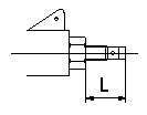
Temporary full load screw adjustment
At reassembly set the distance that the full load screw protrudes at L.
----------
L=14+-0.5mm
----------
L=14+-0.5mm
----------
L=14+-0.5mm
----------
L=14+-0.5mm
Information:
Start By:a. remove oil pump1. Check the main bearing caps for identification for their location and direction in the block. The caps must be installed in the same location and direction from which they were removed. 2. Remove number 2 through number 6 bearing caps (1). Remove thrust plates from the number 4 main bearing.
If the crankshaft is turned in the wrong direction, the tab of the bearing will be pushed between the crankshaft and cylinder block. This can cause damage to either the crankshaft or cylinder block or both.
3. Remove the upper halves of the main bearings by putting Tool (A) in oil hole (2) in the crankshaft. Turn the crankshaft in the direction which will push the end of the bearing with a tab out first.4. Remove the lower halves of the bearings from the caps. Install the bearings dry when the clearance checks are made. Put clean engine oil on the bearings for final assembly.5. Install the new bearings in the caps.6. Install the upper halves of the bearings in the cylinder with Tool (A).
Be sure tabs (3) on the back of the bearings fit in the tab slots of the caps and cylinder block. The serviceman must be very careful to use Plastigage, Tool (B) correctly. The following points must be remembered.
Make sure that the backs of the bearings and the bores are clean and dry.Make sure that the bearing locking tabs are properly seated in their slots.The crankshaft must be free of oil where the Plastigage touches it.If the main bearing clearances are checked with the engine upright or on its side, the crankshaft must be supported. Use a jack under an adjacent crankshaft counterweight and hold the crankshaft against the crown of the bearing. If the crankshaft is not supported, the weight of the crankshaft will cause incorrect readings.Put a piece of Plastigage on the crown of the bearing half that is in the cap. Do not allow the Plastigage to extend over the edge of the bearing.Install the bearing cap using the correct torque-turn specifications. Do not use an impact wrench. Be careful not to dislodge the bearing when the cap is installed.Do not turn the crankshaft with the Plastigage installed.Carefully remove the cap but do not remove the Plastigage. Measure the width of the Plastigage while it is in the bearing cap or on the crankshaft journal. Do this by using the correct scale on the package. Record the measurements.Remove the Plastigage before reinstalling the cap.When using Plastigage, the readings can sometimes be unclear. For example, all parts of the Plastigage are not the same width. Measure the major widths to make sure that they are within the specification range. Also, experience has shown that when checking clearances tighter than 0.10 mm (.004 in) the readings may be low by 0.013 to 0.025 mm (.0005 to .0010 in). Out-of-round journals can give faulty readings. Also, journal taper may be indicated when one end of the Plastigage is wider that the