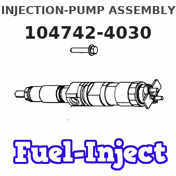
Information injection-pump assembly
ZEXEL
104742-4030
1047424030
NISSAN-DIESEL
1670018T01
1670018t01
Rating:
Cross reference number
ZEXEL
104742-4030
1047424030
NISSAN-DIESEL
1670018T01
1670018t01
Zexel num
Bosch num
Firm num
Name
104742-4030
1670018T01 NISSAN-DIESEL
INJECTION-PUMP ASSEMBLY
FD35 *
FD35 *
Calibration Data:
Adjustment conditions
Test oil
1404 Test oil ISO4113orSAEJ967d
1404 Test oil ISO4113orSAEJ967d
Test oil temperature
degC
45
45
50
Nozzle
105780-0060
Bosch type code
NP-DN0SD1510
Nozzle holder
105780-2150
Opening pressure
MPa
13
13
13.3
Opening pressure
kgf/cm2
133
133
136
Injection pipe
157805-7320
Injection pipe
Inside diameter - outside diameter - length (mm) mm 2-6-450
Inside diameter - outside diameter - length (mm) mm 2-6-450
Joint assembly
157641-4720
Tube assembly
157641-4020
Transfer pump pressure
kPa
20
20
20
Transfer pump pressure
kgf/cm2
0.2
0.2
0.2
Direction of rotation (viewed from drive side)
Right R
Right R
Injection timing adjustment
Pump speed
r/min
1000
1000
1000
Average injection quantity
mm3/st.
61.9
61.4
62.4
Difference in delivery
mm3/st.
4
Basic
*
Oil temperature
degC
50
48
52
Injection timing adjustment_02
Pump speed
r/min
500
500
500
Average injection quantity
mm3/st.
67.7
67.7
67.7
Oil temperature
degC
47
45
49
Injection timing adjustment_03
Pump speed
r/min
700
700
700
Average injection quantity
mm3/st.
56
53.5
58.5
Oil temperature
degC
47
45
49
Injection timing adjustment_04
Pump speed
r/min
1000
1000
1000
Average injection quantity
mm3/st.
61.9
60.9
62.9
Difference in delivery
mm3/st.
4
Basic
*
Oil temperature
degC
50
48
52
Injection timing adjustment_05
Pump speed
r/min
1750
1750
1750
Average injection quantity
mm3/st.
66
63
69
Oil temperature
degC
52
50
54
Injection quantity adjustment
Pump speed
r/min
2000
2000
2000
Average injection quantity
mm3/st.
25.1
22.1
28.1
Basic
*
Oil temperature
degC
50
48
52
Injection quantity adjustment_02
Pump speed
r/min
2200
2200
2200
Average injection quantity
mm3/st.
5
Oil temperature
degC
52
49
55
Injection quantity adjustment_03
Pump speed
r/min
2000
2000
2000
Average injection quantity
mm3/st.
25.1
21.6
28.6
Basic
*
Oil temperature
degC
50
48
52
Governor adjustment
Pump speed
r/min
400
400
400
Average injection quantity
mm3/st.
19.4
17.4
21.4
Difference in delivery
mm3/st.
3.9
Basic
*
Oil temperature
degC
48
46
50
Governor adjustment_02
Pump speed
r/min
350
350
350
Average injection quantity
mm3/st.
17.9
15.4
20.4
Difference in delivery
mm3/st.
3.7
Basic
*
Oil temperature
degC
48
46
50
Timer adjustment
Pump speed
r/min
100
100
100
Average injection quantity
mm3/st.
85
85
125
Basic
*
Oil temperature
degC
48
46
50
Timer adjustment_02
Pump speed
r/min
100
100
100
Average injection quantity
mm3/st.
85
85
125
Oil temperature
degC
48
46
50
Speed control lever angle
Pump speed
r/min
400
400
400
Average injection quantity
mm3/st.
0
0
0
Oil temperature
degC
48
46
50
Remarks
Magnet OFF at idling position
Magnet OFF at idling position
Speed control lever angle_02
Pump speed
r/min
100
100
100
Average injection quantity
mm3/st.
0
0
0
Oil temperature
degC
48
46
50
Remarks
Magnet OFF at idling position
Magnet OFF at idling position
0000000901
Pump speed
r/min
1000
1000
1000
Overflow quantity
cm3/min
300
170
430
Oil temperature
degC
50
48
52
Stop lever angle
Pump speed
r/min
1400
1400
1400
Pressure
kPa
618
598
638
Pressure
kgf/cm2
6.3
6.1
6.5
Basic
*
Oil temperature
degC
50
48
52
Stop lever angle_02
Pump speed
r/min
1000
1000
1000
Pressure
kPa
471
432
510
Pressure
kgf/cm2
4.8
4.4
5.2
Oil temperature
degC
50
48
52
Stop lever angle_03
Pump speed
r/min
1400
1400
1400
Pressure
kPa
618
579
657
Pressure
kgf/cm2
6.3
5.9
6.7
Basic
*
Oil temperature
degC
50
48
52
Stop lever angle_04
Pump speed
r/min
1750
1750
1750
Pressure
kPa
745
706
784
Pressure
kgf/cm2
7.6
7.2
8
Oil temperature
degC
50
48
52
0000001101
Pump speed
r/min
1400
1400
1400
Timer stroke
mm
2.2
2
2.4
Basic
*
Oil temperature
degC
50
48
52
_02
Pump speed
r/min
1400
1400
1400
Timer stroke
mm
2.2
1.8
2.6
Basic
*
Oil temperature
degC
50
48
52
_03
Pump speed
r/min
1600
1600
1600
Timer stroke
mm
3.9
3.3
4.5
Oil temperature
degC
50
48
52
_04
Pump speed
r/min
1750
1750
1750
Timer stroke
mm
4.9
4.4
5.3
Oil temperature
degC
50
48
52
0000001201
Max. applied voltage
V
16
16
16
Test voltage
V
25
24
26
Timing setting
K dimension
mm
3.1
3
3.2
KF dimension
mm
5.8
5.7
5.9
MS dimension
mm
0.7
0.6
0.8
Pre-stroke
mm
0.1
0.08
0.12
Control lever angle alpha
deg.
25
21
29
Control lever angle beta
deg.
33.5
28.5
38.5
Test data Ex:
0000001801 TEMP. ADJUST FULL-LOAD SCREW
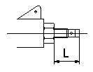
Temporary full load screw adjustment
At reassembly set the distance that the full load screw protrudes at L.
----------
L=14+-0.5mm
----------
L=14+-0.5mm
----------
L=14+-0.5mm
----------
L=14+-0.5mm
0000001901 POTENTIOMETER ADJUSTMENT
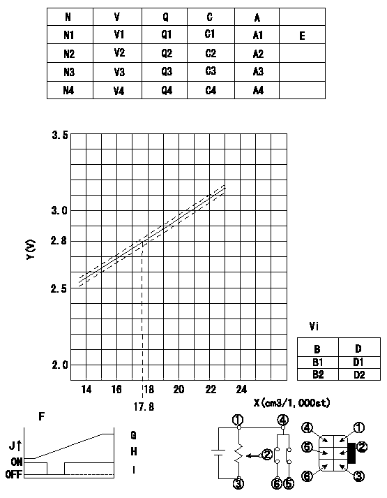
Adjustment of the potentiometer
Measure the injection quantity with the control lever a from the idle position (equal to shim thickness L1) at pump speed N5. Install the potentiometer so that injection quantity and output voltage correspond as shown in the graph.
Confirm at least V5 at full lever position.
Reference value: conversion expression
17.4 < X < 23.5 V+-0.03 = 0.063X+0.94
29>X>23.5 V+-0.03=0.04X+1.48
17.4 > X V = 2.07
29<X V=2.64
A = shim thickness
B = changeover point
C = control lever angle
D = lever position (from idle)
E = adjusting point
Vi = applied voltage
V = potentiometer voltage
X = injection quantity Q
Y = voltage (V)
B1 = idle switch ON to OFF
B2 = full switch OFF to ON
F = potentiometer wiring diagram
G = output between connections (2) and (3)
H = switch OFF to ON at connections 4 and 6.
I = switch ON to OFF at connecting harnesses 4 and 5
J = output
K = idle
N = pump speed
Q = injection quantity
----------
N5=500r/min a=8.8deg L1=5.7mm V5=5V
----------
N1=500r/min N2=500r/min N3=500r/min N4=0r/min V1=(2.07)V V2=2.37+-0.03V V3=(2.74)V V4=0.9+-0.4V Q1=Measure cm3/1,000st Q2=22.2+-4cm3/1,000st Q3=Measure cm3/1,000st Q4=- cm3/1,000st C1=(7)deg C2=(8.8)deg C3=(11)deg C4=0deg A1=(4.5+-0.05)mm A2=(5.7+-0.05)mm A3=(7.1+-0.05)mm A4=0mm Vi=10 V D1=(4.6+-2.6)deg D2=(23.6+-2.6)deg
----------
N5=500r/min a=8.8deg L1=5.7mm V5=5V
----------
N1=500r/min N2=500r/min N3=500r/min N4=0r/min V1=(2.07)V V2=2.37+-0.03V V3=(2.74)V V4=0.9+-0.4V Q1=Measure cm3/1,000st Q2=22.2+-4cm3/1,000st Q3=Measure cm3/1,000st Q4=- cm3/1,000st C1=(7)deg C2=(8.8)deg C3=(11)deg C4=0deg A1=(4.5+-0.05)mm A2=(5.7+-0.05)mm A3=(7.1+-0.05)mm A4=0mm Vi=10 V D1=(4.6+-2.6)deg D2=(23.6+-2.6)deg
0000002001 ACCELERATOR SWITCH ADJ
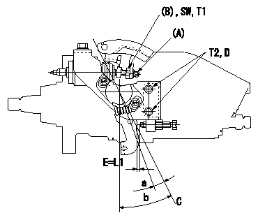
Accelerator switch adjustment
ON - OFF changeover point: from idle to a (shim thickness E = L)
Idle-c: ON
d ~ full: OFF
E = shim thickness
Insert a block gauge thickness L1 (corresponding to lever position a) between the idle set screw and the control lever and set the switch using the screw (A) so that it moves from ON to OFF. Then tighten the nut (B).
C = idle lever position
D = 2 of 2 locations
----------
a=3.5deg c=3.5deg d=3.5deg L=2.3+-0.1mm L1=2.3mm
----------
a=3.5deg b=25+-4deg SW=SW10 T1=5~7N-m(0.5~0.7kgf-m) T2=7~10N-m(0.7~1kgf-m) L1=2.3mm
----------
a=3.5deg c=3.5deg d=3.5deg L=2.3+-0.1mm L1=2.3mm
----------
a=3.5deg b=25+-4deg SW=SW10 T1=5~7N-m(0.5~0.7kgf-m) T2=7~10N-m(0.7~1kgf-m) L1=2.3mm
Information:
Typical Example1. Remove bolts (1) from the alternator bracket.2. Remove the bolts that hold plate (3) and remove the plate.3. Disconnect water line (2) from the air compressor. Turn the water line tee toward the lifting bracket in order to provide clearance to remove the head bolt. 4. Remove bolts (4) and (5) that hold the cylinder head assembly to the cylinder block.5. Fasten a hoist and remove the cylinder head assembly. The weight is approximately 135 kg (300 lb).
Do not put the cylinder head assembly down on a flat surface. This can cause damage to the fuel injection valves.
6. Remove the gasket and seals from the spacer plate.Install Cylinder Head Assembly
Be sure a new gasket has been installed between the spacer plate and the cylinder block. See topic, "Remove & Install Spacer Plate". 1. Thoroughly clean the spacer plate and the bottom surface of the cylinder head assembly. Install a new head gasket, new seals (1) and two O-ring seals (2). 2. Fasten a hoist and put the cylinder head assembly (3) in position on the cylinder block.3. Tighten the bolts in sequence shown in Illustration D11970.
(1) Large bolts (3/4 inch). Put 6V4876 Molycoat Paste Lubricant on bolt threads and between washers and underside of bolt heads.(2) Small bolts (3/8 inch). See Step 4h.4. Install the cylinder head bolts and washers. Tighten the bolts in sequence shown.a. Tighten bolts 1 through 14 in number sequence to 270 25 N m (200 20 lb ft).b. Tighten bolts 1 through 14 in number sequence to 470 20 N m (345 15 lb ft).c. Tighten bolts 1 through 14 in number sequence again to 470 20 N m (345 15 lb ft).d. Install the rocker arm shafts for the engine valves and the remaining (3/4 in) bolts and/or compression brake studs.e. Tighten bolts 15 through 26 in number sequence to 270 25 N m (200 20 lb ft).f. Tighten bolts 15 through 26 in number sequence to 450 20 N m (330 15 lb ft).g. Tighten bolts 15 through 26 in number sequence again to 450 20 N m (330 15 lb ft).h. Tighten the thirteen small bolts (2) to 45 7 N m (33 5 lb ft).5. Make an adjustment to the valves to have a clearance of 0.38 mm (.015 in) for intake and 0.76 mm (.030 in) for exhaust. Tighten the locknuts for the valve adjustment screws to a torque of 28 4 N m (21 3 lb ft).6. Install the valve cover bases and the inner fuel lines. See topic, "Install Rocker Shaft Assemblies & Push Rods".7. Install the valve covers. See topic, "Install Valve Covers".
Typical Example8. Install plate (4).9. Connect the water line to the air compressor.10. Install bolts (5) for the alternator bracket.End By:a. install exhaust manifoldb. install fuel injection linesc. install aftercooler housingd. install water temperature regulatore. install rocker shaft assemblies and push rods
Have questions with 104742-4030?
Group cross 104742-4030 ZEXEL
Nissan-Diesel
104742-4030
1670018T01
INJECTION-PUMP ASSEMBLY
FD35
FD35