Information injection-pump assembly
ZEXEL
104742-4010
1047424010
NISSAN-DIESEL
1670001T03
1670001t03
Rating:
Cross reference number
ZEXEL
104742-4010
1047424010
NISSAN-DIESEL
1670001T03
1670001t03
Zexel num
Bosch num
Firm num
Name
104742-4010
1670001T03 NISSAN-DIESEL
INJECTION-PUMP ASSEMBLY
FD35
FD35
Calibration Data:
Adjustment conditions
Test oil
1404 Test oil ISO4113orSAEJ967d
1404 Test oil ISO4113orSAEJ967d
Test oil temperature
degC
45
45
50
Nozzle
105000-2010
Bosch type code
NP-DN12SD12TT
Nozzle holder
105780-2080
Opening pressure
MPa
14.7
14.7
15.19
Opening pressure
kgf/cm2
150
150
155
Injection pipe
Inside diameter - outside diameter - length (mm) mm 2-6-840
Inside diameter - outside diameter - length (mm) mm 2-6-840
Transfer pump pressure
kPa
20
20
20
Transfer pump pressure
kgf/cm2
0.2
0.2
0.2
Direction of rotation (viewed from drive side)
Right R
Right R
Injection timing adjustment
Pump speed
r/min
1000
1000
1000
Average injection quantity
mm3/st.
60.3
59.8
60.8
Difference in delivery
mm3/st.
4
Basic
*
Injection timing adjustment_02
Pump speed
r/min
2000
2000
2000
Average injection quantity
mm3/st.
27.8
24.3
31.3
Injection timing adjustment_03
Pump speed
r/min
1750
1750
1750
Average injection quantity
mm3/st.
52.3
46.8
57.8
Injection timing adjustment_04
Pump speed
r/min
1000
1000
1000
Average injection quantity
mm3/st.
60.3
59.3
61.3
Injection timing adjustment_05
Pump speed
r/min
700
700
700
Average injection quantity
mm3/st.
57.1
53.6
60.6
Injection timing adjustment_06
Pump speed
r/min
500
500
500
Average injection quantity
mm3/st.
69.1
62.6
75.6
Injection quantity adjustment
Pump speed
r/min
2000
2000
2000
Average injection quantity
mm3/st.
27.8
24.8
30.8
Basic
*
Injection quantity adjustment_02
Pump speed
r/min
2200
2200
2200
Average injection quantity
mm3/st.
5
Governor adjustment
Pump speed
r/min
325
325
325
Average injection quantity
mm3/st.
17.5
15.5
19.5
Difference in delivery
mm3/st.
3.5
Basic
*
Governor adjustment_02
Pump speed
r/min
325
325
325
Average injection quantity
mm3/st.
17.5
15.5
19.5
Governor adjustment_03
Pump speed
r/min
500
500
500
Average injection quantity
mm3/st.
3
Timer adjustment
Pump speed
r/min
100
100
100
Average injection quantity
mm3/st.
105
85
125
Basic
*
Speed control lever angle
Pump speed
r/min
325
325
325
Average injection quantity
mm3/st.
0
0
0
Remarks
Magnet OFF
Magnet OFF
0000000901
Pump speed
r/min
1000
1000
1000
Overflow quantity
cm3/min
300
168
432
Stop lever angle
Pump speed
r/min
1400
1400
1400
Pressure
kPa
617.5
598
637
Pressure
kgf/cm2
6.3
6.1
6.5
Basic
*
Stop lever angle_02
Pump speed
r/min
1000
1000
1000
Pressure
kPa
470.5
441
500
Pressure
kgf/cm2
4.8
4.5
5.1
Stop lever angle_03
Pump speed
r/min
1400
1400
1400
Pressure
kPa
617.5
598
637
Pressure
kgf/cm2
6.3
6.1
6.5
Stop lever angle_04
Pump speed
r/min
1750
1750
1750
Pressure
kPa
755.5
726
785
Pressure
kgf/cm2
7.7
7.4
8
0000001101
Pump speed
r/min
1400
1400
1400
Timer stroke
mm
2.2
2
2.4
Basic
*
_02
Pump speed
r/min
1400
1400
1400
Timer stroke
mm
2.2
1.9
2.5
_03
Pump speed
r/min
1600
1600
1600
Timer stroke
mm
3.9
3.2
4.6
_04
Pump speed
r/min
1750
1750
1750
Timer stroke
mm
4.8
4.3
5.3
0000001201
Max. applied voltage
V
16
16
16
Test voltage
V
25
24
26
Timing setting
K dimension
mm
3.1
3
3.2
KF dimension
mm
5.8
5.7
5.9
MS dimension
mm
0.7
0.6
0.8
Pre-stroke
mm
0.1
0.1
0.1
Control lever angle alpha
deg.
25
21
29
Control lever angle beta
deg.
36
31
41
Test data Ex:
0000001801 ACCELERATOR SWITCH ADJ
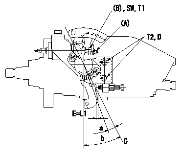
Accelerator switch adjustment
ON - OFF changeover point: from idle to a (shim thickness E = L)
Idle-c: ON
d ~ full: OFF
E = shim thickness
Insert a block gauge thickness L1 (corresponding to lever position a) between the idle set screw and the control lever and set the switch using the screw (A) so that it moves from ON to OFF. Then tighten the nut (B).
C = idle lever position
D = 2 of 2 locations
----------
a=5deg c=5deg d=5deg L=3.3mm L1=3.3mm
----------
a=5deg b=25+-4deg SW=SW10 T1=5~7N-m(0.5~0.7kgf-m) T2=7~10N-m(0.7~1kgf-m) L1=3.3mm
----------
a=5deg c=5deg d=5deg L=3.3mm L1=3.3mm
----------
a=5deg b=25+-4deg SW=SW10 T1=5~7N-m(0.5~0.7kgf-m) T2=7~10N-m(0.7~1kgf-m) L1=3.3mm
Information:
2. Loosen two hose clamps (1).3. Remove hose (2). 4. Remove two bolts (3).5. Remove elbow (5).6. Remove fumes disposal tube (4) for access to the water pump.7. Disconnect coolant conditioner hose (6).8. Remove heater hose (12) (previously removed).9. Loosen hose clamp (15).10. Disconnect lower radiator hose (13).11. Remove two bolts (14) from oil cooler. Check gasket for wear or damage. Replace if necessary.12. Remove four bolts (10).13. Remove water pump cover (11).14. Remove seven long bolts (7).15. Reposition air conditioning lines and oil line (8) after bolts are removed.16. Remove water pump (9). Check seals and O-rings for wear and damage before installation, replace as necessary. For installation of the water pump, reverse the removal steps.17. Fill the cooling system with coolant to correct level. See the Operation & Maintenance Manual.Disassemble Water Pump
*Part of 1P510 Driver Group.Start By:a. remove water pump The water pump seal can be replaced without removing the water pump from the engine. An intermittent leakage of a small amount of coolant from the hole in the water pump housing is not an indication of a water pump seal failure. This is required to provide lubrication for the seal. Replace the water pump seal only if a large amount of leakage or a constant flow of coolant is observed draining from the water pump housing.1. Remove O-ring seal (1) from the adapter.2. Remove adapter (2) from the housing. Remove the O-ring seal from the outside diameter of the adapter.3. Remove bolt (3) and the retainer that hold the impeller on the shaft. 4. Use Tool (A) to remove impeller (4) from the shaft. 5. Remove the spring and seal (5) from the shaft. 6. Remove four bolts (7) from retainer (6) that hold the shaft assembly to the pump housing.7. Remove O-ring seal (8) from the housing. 8. Remove gear and shaft assembly (10) from the housing.9. Remove bolt (9) and the retainer from the shaft assembly. 10. Use a press to remove the shaft assembly from gear (11). Remove the retainer from the shaft assembly. 11. Remove bearing (13), spacer (14) and bearing (12) from the shaft. 12. Remove lip-type seal (15) from the housing.13. Turn the housing over, and remove ceramic ring (16) and the seal.Assemble Water Pump
1. Use 6V1541 Quick Cure Primer to clean shaft (8) and the seal counterbore in the pump housing.2. Install bearing (4), spacer (3) and bearing (2) on shaft (8).3. Put retainer (1) and gear (7) in position on the shaft assembly. Install retainer (6) and bolt (5). 4. Use Tool (A) to install the lip-type seal in the housing as shown. Put a small amount of clean SAE 30 Oil on the lip of the seal. 5. Install a new O-ring seal (10) on the housing.6. Put shaft assembly (9) in position in the housing. Install the bolts that hold the retainer to the housing.
Clean water only is permitted for use as a lubricant for assistance at installation. Do not damage or put hands on
Have questions with 104742-4010?
Group cross 104742-4010 ZEXEL
Nissan-Diesel
104742-4010
1670001T03
INJECTION-PUMP ASSEMBLY
FD35
FD35