Information injection-pump assembly
BOSCH
F 01G 09W 0F9
f01g09w0f9
ZEXEL
104742-3001
1047423001
MITSUBISHI-HEAV
32A6527310
32a6527310

Rating:
Cross reference number
BOSCH
F 01G 09W 0F9
f01g09w0f9
ZEXEL
104742-3001
1047423001
MITSUBISHI-HEAV
32A6527310
32a6527310
Zexel num
Bosch num
Firm num
Name
104742-3001
F 01G 09W 0F9
32A6527310 MITSUBISHI-HEAV
INJECTION-PUMP ASSEMBLY
S4S-DT
S4S-DT
Calibration Data:
Adjustment conditions
Test oil
1404 Test oil ISO4113orSAEJ967d
1404 Test oil ISO4113orSAEJ967d
Test oil temperature
degC
45
45
50
Nozzle
105780-0060
Bosch type code
NP-DN0SD1510
Nozzle holder
105780-2150
Opening pressure
MPa
13
13
13.3
Opening pressure
kgf/cm2
133
133
136
Injection pipe
157805-7320
Injection pipe
Inside diameter - outside diameter - length (mm) mm 2-6-450
Inside diameter - outside diameter - length (mm) mm 2-6-450
Joint assembly
157641-4720
Tube assembly
157641-4020
Transfer pump pressure
kPa
20
20
20
Transfer pump pressure
kgf/cm2
0.2
0.2
0.2
Direction of rotation (viewed from drive side)
Right R
Right R
(Solenoid timer adjustment condition)
With S/T O-ring; S/T OFF. OFF
With S/T O-ring; S/T OFF. OFF
Timer measuring device installation position
Low pressure side LOW PRESSURE SIDE
Low pressure side LOW PRESSURE SIDE
Injection timing adjustment
Pump speed
r/min
900
900
900
Average injection quantity
mm3/st.
119.7
119.2
120.2
Difference in delivery
mm3/st.
11
Basic
*
Oil temperature
degC
50
48
52
Injection timing adjustment_02
Pump speed
r/min
500
500
500
Average injection quantity
mm3/st.
75.7
69.2
82.2
Oil temperature
degC
48
46
50
Injection timing adjustment_03
Pump speed
r/min
900
900
900
Average injection quantity
mm3/st.
119.7
117.2
122.2
Difference in delivery
mm3/st.
11.5
Basic
*
Oil temperature
degC
50
48
52
Injection timing adjustment_04
Pump speed
r/min
1100
1100
1100
Average injection quantity
mm3/st.
126.5
121
132
Oil temperature
degC
50
48
52
Injection timing adjustment_05
Pump speed
r/min
1250
1250
1250
Average injection quantity
mm3/st.
123.5
118
129
Oil temperature
degC
50
48
52
Injection quantity adjustment
Pump speed
r/min
1425
1425
1425
Average injection quantity
mm3/st.
5
Basic
*
Oil temperature
degC
50
48
52
Injection quantity adjustment_02
Pump speed
r/min
1425
1425
1425
Average injection quantity
mm3/st.
6.5
Basic
*
Oil temperature
degC
50
48
52
Injection quantity adjustment_03
Pump speed
r/min
1300
1300
1300
Average injection quantity
mm3/st.
117.9
117.9
Oil temperature
degC
50
48
52
Remarks
(check)
(check)
Governor adjustment
Pump speed
r/min
595
595
595
Average injection quantity
mm3/st.
8.1
6.1
10.1
Difference in delivery
mm3/st.
3
Basic
*
Oil temperature
degC
50
48
52
Governor adjustment_02
Pump speed
r/min
595
595
595
Average injection quantity
mm3/st.
8.1
5.6
10.6
Difference in delivery
mm3/st.
3.5
Basic
*
Oil temperature
degC
50
48
52
Timer adjustment
Pump speed
r/min
100
100
100
Average injection quantity
mm3/st.
120
95
145
Basic
*
Oil temperature
degC
48
46
50
Remarks
Full
Full
Timer adjustment_02
Pump speed
r/min
100
100
100
Average injection quantity
mm3/st.
120
95
145
Oil temperature
degC
48
46
50
Remarks
Full
Full
Speed control lever angle
Pump speed
r/min
595
595
595
Average injection quantity
mm3/st.
0
0
0
Oil temperature
degC
50
48
52
Remarks
Magnet OFF at idling position
Magnet OFF at idling position
Speed control lever angle_02
Pump speed
r/min
595
595
595
Average injection quantity
mm3/st.
0
0
0
Oil temperature
degC
50
48
52
Remarks
Magnet ON at idling position and stop lever operate
Magnet ON at idling position and stop lever operate
0000000901
Pump speed
r/min
1250
1250
1250
Overflow quantity with S/T ON
cm3/min
540
410
670
Oil temperature
degC
50
48
52
Stop lever angle
Pump speed
r/min
1250
1250
1250
Pressure with S/T ON
kPa
696
647
745
Pressure with S/T ON
kgf/cm2
7.1
6.6
7.6
Pressure with S/T OFF
kPa
530
510
550
Pressure with S/T OFF
kgf/cm2
5.4
5.2
5.6
Basic
*
Oil temperature
degC
50
48
52
Remarks
OFF
OFF
Stop lever angle_02
Pump speed
r/min
900
900
900
Pressure with S/T OFF
kPa
402
353
451
Pressure with S/T OFF
kgf/cm2
4.1
3.6
4.6
Oil temperature
degC
50
48
52
Stop lever angle_03
Pump speed
r/min
1100
1100
1100
Pressure with S/T OFF
kPa
481
432
530
Pressure with S/T OFF
kgf/cm2
4.9
4.4
5.4
Oil temperature
degC
50
48
52
Stop lever angle_04
Pump speed
r/min
1250
1250
1250
Pressure with S/T ON
kPa
696
637
755
Pressure with S/T ON
kgf/cm2
7.1
6.5
7.7
Pressure with S/T OFF
kPa
530
501
559
Pressure with S/T OFF
kgf/cm2
5.4
5.1
5.7
Basic
*
Oil temperature
degC
50
48
52
Remarks
OFF
OFF
0000001101
Pump speed
r/min
1250
1250
1250
Timer stroke with S/T ON
mm
4.6
4.1
5.1
Timer stroke with S/T OFF
mm
2.9
2.7
3.1
Basic
*
Oil temperature
degC
50
48
52
Remarks
OFF
OFF
_02
Pump speed
r/min
900
900
900
Timer stroke with S/T OFF
mm
1.2
0.5
1.9
Oil temperature
degC
50
48
52
_03
Pump speed
r/min
1100
1100
1100
Timer stroke with S/T OFF
mm
2.2
1.6
2.8
Oil temperature
degC
50
48
52
_04
Pump speed
r/min
1250
1250
1250
Timer stroke with S/T ON
mm
4.6
3.9
5.3
Timer stroke with S/T OFF
mm
2.9
2.5
3.3
Basic
*
Oil temperature
degC
50
48
52
Remarks
OFF
OFF
0000001201
Max. applied voltage
V
8
8
8
Test voltage
V
13
12
14
0000001401
Pump speed
r/min
1250
1250
1250
Average injection quantity
mm3/st.
94
92
96
Timer stroke TA
mm
0.3
0
0.6
Timer stroke variation dT
mm
2.6
2.6
2.6
Basic
*
Oil temperature
degC
50
48
52
_02
Pump speed
r/min
1250
1250
1250
Average injection quantity
mm3/st.
112
110
114
Timer stroke TA
mm
2.7
2.7
Timer stroke variation dT
mm
0.2
0.2
0.2
Oil temperature
degC
50
48
52
Remarks
(check)
(check)
_03
Pump speed
r/min
1250
1250
1250
Average injection quantity
mm3/st.
94
91.5
96.5
Timer stroke TA
mm
0.3
0
0.8
Timer stroke variation dT
mm
2.6
2.6
2.6
Basic
*
Oil temperature
degC
50
48
52
_04
Pump speed
r/min
1250
1250
1250
Average injection quantity
mm3/st.
25
22.5
27.5
Timer stroke TA
mm
3.5
2.7
4.3
Timer stroke variation dT
mm
0.6
0.6
0.6
Oil temperature
degC
50
48
52
Timing setting
K dimension
mm
3.1
3
3.2
KF dimension
mm
5.5
5.4
5.6
MS dimension
mm
0.9
0.8
1
Pre-stroke
mm
0.45
0.43
0.47
Control lever angle alpha
deg.
16
12
20
Control lever angle beta
deg.
30
25
35
Test data Ex:
0000001801 TAMPER PROOF

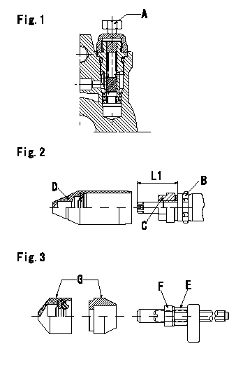
Tamperproof installation procedure
A:Position of break
B:Rubber vibration damper
C:Nut
D:Cap
E:Nut
F:Nut
G:Cap
L1:Inspection dimension
Fig. 1 Regulating valve seal
1) Target breaking torque T1
2) Maximum allowable breaking torque T2
3) Because the cap and the regulating valve are fixed using the MEC process, the bolt cannot be loosened after the bolt has been broken.
Fig.2 Full load adjusting screw
1) Confirm the position of the rubber vibration damper (B) and then tighten nut (C) to the torque T3.
Fig. 3 Maximum speed adjusting screw
1) Tighten nut (E) to the torque T4.
2) To prevent nut (E) from turning together, fix (E) using the tool, then tighten nut (F) to torque T4.
----------
L1=23~28mm T1=5~6.9N-m(0.5~0.69kgf-m) T2=9N-m(0.9kgf-m) T3=7~9N-m(0.7~0.9kgf-m) T4=6~9N-m(0.6~0.9kgf-m)
----------
L1=23~28mm
----------
L1=23~28mm T1=5~6.9N-m(0.5~0.69kgf-m) T2=9N-m(0.9kgf-m) T3=7~9N-m(0.7~0.9kgf-m) T4=6~9N-m(0.6~0.9kgf-m)
----------
L1=23~28mm
Information:
1. Defective Upper O-ring On Unit Injectors Or Leaking Unit Injector Using the fuel priming pump, pressurize the fuel system to 689 kPa (100 psi). Check for fuel on the top deck of the cylinder head (a small amount of leakage is normal from the injector plunger barrel area after 5 minutes of constant pressure). If fuel is found, drain the fuel supply manifold. Remove each unit injector (see 3176 Vehicular Diesel Engine Disassembly and Assembly, Form No. SENR4965), and check for a defective upper O-ring on the unit injector or if the unit injector itself is leaking.A bad injector to sleeve seat causes combustion gas leakage that can damage the injector O-rings. Inspect injector hold down bolt thread depth for a minimum of 25 mm (.984 in) of thread depth in the cylinder head.Testing of the injectors must be done off of the engine. Use the 1U6661 Pop (Injector) Tester Group with a 1U6663 Injector Holding Block, and a 1U6665 Power Supply, to test the injectors. For the test procedure refer to Special Instruction, Form No. SEHS8867, Using The 1U6661 Pop (Injector) Tester. For test specifications refer to Special Instruction, Form No. SEHS8804, Unit Injector Test Specifications for 1.7 Liter Engines. Inspect and repair as necessary the sealing surface (seat) of the injector sleeve in the cylinder head when removing and installing an injector. The injector sealing surface (seat) must be free of scratches or evidence of combustion products. If it is necessary to rework (ream) or replace the sleeve use 4C4054 Tool Group and refer to Special Instruction, Form No. SEHS9246, Using The 4C4054 Unit Injector Sleeve Replacement Tool Group.2. Injector Not Seated Properly A bad injector to sleeve seat causes combustion gas leakage that can damage the injector o-rings. Inspect injector hold down bolt thread depth for a minimum of 25 mm (.984 in) of thread depth in the cylinder head.Torque fuel injector hold down bolt to 33 7 N m (24 5 lb ft). Inspect and repair as necessary the sealing surface (seat) of the injector sleeve in the cylinder head when removing and installing an injector. The injector sealing surface (seat) must be free of scratches or evidence of combustion products. If it is necessary to rework (ream) or replace the sleeve use 4C4054 Tool Group and refer to Special Instruction, Form No. SEHS9246, Using The 4C4054 Unit Injector Sleeve Replacement Tool Group.3. Crack(s) In Cylinder Head Pressurize the fuel gallery and check for crack(s). Crack(s) between the cylinder head fuel passages and passages open to the crankcase will allow fuel to enter the crankcase.4. Porosity In Cylinder HeadPressurize the fuel gallery and check for porosity. Leakage may be due to the proximity of the hole to internal fuel passages.
Have questions with 104742-3001?
Group cross 104742-3001 ZEXEL
Mitsubishi-Heav
104742-3001
F 01G 09W 0F9
32A6527310
INJECTION-PUMP ASSEMBLY
S4S-DT
S4S-DT