Information injection-pump assembly
ZEXEL
104742-1611
1047421611
ISUZU
8971918561
8971918561

Rating:
Cross reference number
ZEXEL
104742-1611
1047421611
ISUZU
8971918561
8971918561
Zexel num
Bosch num
Firm num
Name
Calibration Data:
Adjustment conditions
Test oil
1404 Test oil ISO4113orSAEJ967d
1404 Test oil ISO4113orSAEJ967d
Test oil temperature
degC
45
45
50
Nozzle
105780-0060
Bosch type code
NP-DN0SD1510
Nozzle holder
105780-2150
Opening pressure
MPa
13
13
13.3
Opening pressure
kgf/cm2
133
133
136
Injection pipe
157805-7320
Injection pipe
Inside diameter - outside diameter - length (mm) mm 2-6-450
Inside diameter - outside diameter - length (mm) mm 2-6-450
Joint assembly
157641-4720
Tube assembly
157641-4020
Transfer pump pressure
kPa
20
20
20
Transfer pump pressure
kgf/cm2
0.2
0.2
0.2
Direction of rotation (viewed from drive side)
Left L
Left L
Injection timing adjustment
Pump speed
r/min
1180
1180
1180
Average injection quantity
mm3/st.
53.8
53.3
54.3
Difference in delivery
mm3/st.
4
Basic
*
Oil temperature
degC
50
48
52
Injection timing adjustment_02
Pump speed
r/min
500
500
500
Average injection quantity
mm3/st.
36
32
40
Oil temperature
degC
48
46
50
Injection timing adjustment_03
Pump speed
r/min
750
750
750
Average injection quantity
mm3/st.
41.7
37.7
45.7
Oil temperature
degC
50
48
52
Injection timing adjustment_04
Pump speed
r/min
1180
1180
1180
Average injection quantity
mm3/st.
53.8
52.8
54.8
Difference in delivery
mm3/st.
4
Basic
*
Oil temperature
degC
50
48
52
Injection timing adjustment_05
Pump speed
r/min
2000
2000
2000
Average injection quantity
mm3/st.
63.6
59.1
68.1
Oil temperature
degC
50
48
52
Injection quantity adjustment
Pump speed
r/min
2350
2350
2350
Average injection quantity
mm3/st.
16.6
13.6
19.6
Difference in delivery
mm3/st.
4
Basic
*
Oil temperature
degC
52
50
54
Injection quantity adjustment_02
Pump speed
r/min
2700
2700
2700
Average injection quantity
mm3/st.
5
Oil temperature
degC
55
52
58
Injection quantity adjustment_03
Pump speed
r/min
2350
2350
2350
Average injection quantity
mm3/st.
16.6
13.6
19.6
Difference in delivery
mm3/st.
4
Basic
*
Oil temperature
degC
52
50
54
Governor adjustment
Pump speed
r/min
385
385
385
Average injection quantity
mm3/st.
8.6
6.6
10.6
Difference in delivery
mm3/st.
2
Basic
*
Oil temperature
degC
48
46
50
Governor adjustment_02
Pump speed
r/min
385
385
385
Average injection quantity
mm3/st.
8.6
6.6
10.6
Difference in delivery
mm3/st.
2
Basic
*
Oil temperature
degC
48
46
50
Timer adjustment
Pump speed
r/min
100
100
100
Average injection quantity
mm3/st.
60
60
100
Oil temperature
degC
48
46
50
Remarks
Full
Full
Timer adjustment_02
Pump speed
r/min
100
100
100
Average injection quantity
mm3/st.
60
60
100
Oil temperature
degC
48
46
50
Remarks
Full
Full
Speed control lever angle
Pump speed
r/min
375
375
375
Average injection quantity
mm3/st.
0
0
0
Oil temperature
degC
48
46
50
Remarks
Magnet OFF at idling position
Magnet OFF at idling position
0000000901
Pump speed
r/min
1400
1400
1400
Overflow quantity
cm3/min
600
470
730
Oil temperature
degC
50
48
52
Stop lever angle
Pump speed
r/min
1400
1400
1400
Pressure
kPa
412
392
432
Pressure
kgf/cm2
4.2
4
4.4
Basic
*
Oil temperature
degC
50
48
52
Stop lever angle_02
Pump speed
r/min
1400
1400
1400
Pressure
kPa
412
392
432
Pressure
kgf/cm2
4.2
4
4.4
Basic
*
Oil temperature
degC
50
48
52
Stop lever angle_03
Pump speed
r/min
1900
1900
1900
Pressure
kPa
569
540
598
Pressure
kgf/cm2
5.8
5.5
6.1
Oil temperature
degC
50
48
52
0000001101
Pump speed
r/min
1400
1400
1400
Timer stroke
mm
3.3
3.1
3.5
Basic
*
Oil temperature
degC
50
48
52
_02
Pump speed
r/min
900
900
900
Timer stroke with S/T ON
mm
0.5
Oil temperature
degC
50
48
52
_03
Pump speed
r/min
1400
1400
1400
Timer stroke with S/T ON
mm
3.3
3.1
3.5
Basic
*
Oil temperature
degC
50
48
52
_04
Pump speed
r/min
1600
1600
1600
Timer stroke with S/T ON
mm
4.6
4.2
5
Oil temperature
degC
50
48
52
_05
Pump speed
r/min
1900
1900
1900
Timer stroke with S/T ON
mm
6.1
5.8
6.5
Oil temperature
degC
50
48
52
0000001201
Max. applied voltage
V
8
8
8
Test voltage
V
13
12
14
Timing setting
K dimension
mm
3.6
3.5
3.7
KF dimension
mm
5.4
5.3
5.5
MS dimension
mm
0.7
0.6
0.8
Pre-stroke
mm
0.2
0.18
0.22
Control lever angle alpha
deg.
18
14
22
Control lever angle beta
deg.
35
30
40
Test data Ex:
0000001801 V-FICD ADJUSTMENT

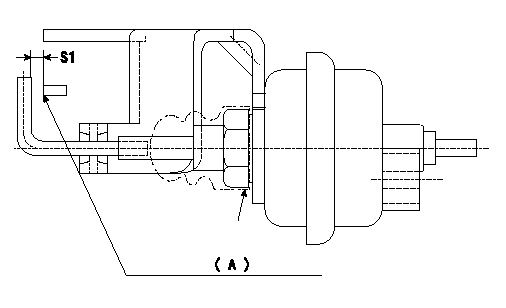
Adjustment of the V-FICD
1. Adjust the actuator rod to obtain S1.
2. Apply negative pressure P1 kPa {P2 mmHg} to the actuator and confirm that it moves through its full stroke.
(A) Control lever (Idling position)
----------
S1=1+1mm P1=-53.3kPa P2=-400mmHg
----------
S1=1+1mm
----------
S1=1+1mm P1=-53.3kPa P2=-400mmHg
----------
S1=1+1mm
Information:
3306 New Scroll Fuel System (NSFS)
See the service manual for your engine for other adjusting procedures.
Rack Adjustment For Engines With NSFS
Rear Of Governor
1. Opening for variable power actuator.1. Remove the variable power actuator from the rear of the governor.2. Adjust the high power fuel setting using the standard fuel system setting procedure in the service manual.For the correct fuel setting specifications, see the Engine Information Plate or the FUEL SETTING AND RELATED INFORMATION FICHE.
6V7941 Compressor Assembly
Governor And Compressor
2. 6V7941 Compressor Assembly.3. Remove the 6V7941 Compressor Assembly (2) and replace the plug in the rear of the governor housing.
Variable Power Actuator
3. Rod. 4. Washered nut. 5. Jam nut. 6. Dust cover.4. Remove the dust cover (6) from the variable power actuator. Loosen the jam nut (5) on the rod (3). Tighten the washered nut (4) to put rod (3) in the fully retracted position.
Governor And Actuator
3. Rod. 4. Washered nut. 5. Jam nut. 7. Actuator.5. Install actuator (7) in governor housing opening (1).6. Move the governor control to the high idle position and hold or fasten the governor control in this position.7. Extend the actuator rod (3), by loosening the washered nut (4), to achieve a minimum dial indicator reading of 2.0 mm (.08 in.) less than the desired low power fuel setting.EXAMPLE: If the low power rack adjustment specification is 3.0 mm (.12 in.), the actuator rod (3) must be adjusted to obtain a dial indicator reading of 1.0 mm (.04 in.).8. Tighten the washered nut (4), to retract the actuator rod (3) and increase the dial indicator reading to the specified low power fuel setting.For the correct fuel setting specifications, see the Engine Information Plate or the FUEL SETTING AND RELATED INFORMATION FICHE.9. If the low power fuel setting is exceeded, repeat steps 7 and 8.10. Tighten the jam nut (5) on the actuator rod (3) and install the dust cover (6).3304 SMFS Air Only Actuator
See the service manual for your engine for other testing and adjusting procedures.
Rack Adjustment For Engines With Sleeve Metering Fuel System (SMFS)
1. Remove the variable power actuator (1) from the rear of the governor (2).2. Use the fuel setting procedure in the service manual and adjust the high power fuel setting screw.For the correct fuel setting specifications, see the Engine Information Plate or the FUEL SETTING AND RELATED INFORMATION FICHE.3. Install the variable power actuator (1).4. Remove the back cover (6) from the actuator (1) to expose the adjustment pin (5).5. Move the governor control shaft to the high idle position.6. Turn the adjustment pin (5) clockwise to adjust the variable power control rod (8) to the fully EXTENDED position.7. To adjust the low power setting, turn the adjustment pin (5) counterclockwise to retract rod (8). Retract the rod (8) until the rack setting is decreased to the specified setting.For the correct fuel setting specifications, see the Engine Information Plate or the FUEL SETTING AND RELATED INFORMATION FICHE.8. Replace cover (6) on the variable power actuator (6).
Governor And Variable Power Actuator
1. Variable