Information injection-pump assembly
ZEXEL
104742-1191
1047421191
ISUZU
8943427071
8943427071

Rating:
Cross reference number
ZEXEL
104742-1191
1047421191
ISUZU
8943427071
8943427071
Zexel num
Bosch num
Firm num
Name
Calibration Data:
Adjustment conditions
Test oil
1404 Test oil ISO4113orSAEJ967d
1404 Test oil ISO4113orSAEJ967d
Test oil temperature
degC
45
45
50
Nozzle
105000-2010
Bosch type code
NP-DN12SD12TT
Nozzle holder
105780-2080
Opening pressure
MPa
14.7
14.7
15.19
Opening pressure
kgf/cm2
150
150
155
Injection pipe
Inside diameter - outside diameter - length (mm) mm 2-6-840
Inside diameter - outside diameter - length (mm) mm 2-6-840
Transfer pump pressure
kPa
20
20
20
Transfer pump pressure
kgf/cm2
0.2
0.2
0.2
Direction of rotation (viewed from drive side)
Right R
Right R
Injection timing adjustment
Pump speed
r/min
1050
1050
1050
Average injection quantity
mm3/st.
65.1
64.6
65.6
Difference in delivery
mm3/st.
4
Basic
*
Injection timing adjustment_02
Pump speed
r/min
1900
1900
1900
Average injection quantity
mm3/st.
16.7
13.2
20.2
Injection timing adjustment_03
Pump speed
r/min
1750
1750
1750
Average injection quantity
mm3/st.
65.3
59.8
70.8
Injection timing adjustment_04
Pump speed
r/min
1400
1400
1400
Average injection quantity
mm3/st.
63
59
67
Injection timing adjustment_05
Pump speed
r/min
1050
1050
1050
Average injection quantity
mm3/st.
65.1
64.1
66.1
Injection timing adjustment_06
Pump speed
r/min
700
700
700
Average injection quantity
mm3/st.
55.2
51.2
59.2
Injection timing adjustment_07
Pump speed
r/min
400
400
400
Average injection quantity
mm3/st.
65.3
60.3
70.3
Injection quantity adjustment
Pump speed
r/min
1900
1900
1900
Average injection quantity
mm3/st.
16.6
13.6
19.6
Difference in delivery
mm3/st.
7
Basic
*
Injection quantity adjustment_02
Pump speed
r/min
2000
2000
2000
Average injection quantity
mm3/st.
8
Governor adjustment
Pump speed
r/min
350
350
350
Average injection quantity
mm3/st.
9.4
7.4
11.4
Difference in delivery
mm3/st.
2
Basic
*
Governor adjustment_02
Pump speed
r/min
450
450
450
Average injection quantity
mm3/st.
3
Governor adjustment_03
Pump speed
r/min
350
350
350
Average injection quantity
mm3/st.
9.4
7.4
11.4
Timer adjustment
Pump speed
r/min
100
100
100
Average injection quantity
mm3/st.
80
80
Basic
*
Speed control lever angle
Pump speed
r/min
350
350
350
Average injection quantity
mm3/st.
0
0
0
Remarks
Magnet OFF
Magnet OFF
Speed control lever angle_02
Pump speed
r/min
100
100
100
Average injection quantity
mm3/st.
0
0
0
Remarks
Magnet OFF
Magnet OFF
0000000901
Pump speed
r/min
1600
1600
1600
Overflow quantity with S/T OFF
cm3/min
621
492
750
Stop lever angle
Pump speed
r/min
1600
1600
1600
Pressure
kPa
588.5
569
608
Pressure
kgf/cm2
6
5.8
6.2
Basic
*
Stop lever angle_02
Pump speed
r/min
1600
1600
1600
Pressure with S/T OFF
kPa
588.5
569
608
Pressure with S/T OFF
kgf/cm2
6
5.8
6.2
Stop lever angle_03
Pump speed
r/min
1750
1750
1750
Pressure with S/T OFF
kPa
637.5
608
667
Pressure with S/T OFF
kgf/cm2
6.5
6.2
6.8
0000001101
Pump speed
r/min
1600
1600
1600
Timer stroke
mm
3
2.8
3.2
Basic
*
_02
Pump speed
r/min
850
850
850
Timer stroke with S/T ON
mm
0.5
0.5
_03
Pump speed
r/min
1450
1450
1450
Timer stroke with S/T OFF
mm
0.5
_04
Pump speed
r/min
1500
1500
1500
Timer stroke with S/T OFF
mm
0.9
0.3
1.5
_05
Pump speed
r/min
1600
1600
1600
Timer stroke with S/T OFF
mm
3
2.7
3.3
_06
Pump speed
r/min
1750
1750
1750
Timer stroke with S/T OFF
mm
5.7
5.3
6.1
0000001201
Max. applied voltage
V
16
16
16
Test voltage
V
25
24
26
Timing setting
K dimension
mm
3.1
3
3.2
KF dimension
mm
5.5
5.4
5.6
MS dimension
mm
0.9
0.8
1
Control lever angle alpha
deg.
50
46
54
Control lever angle beta
deg.
37
32
42
Test data Ex:
0000001801 Temp. adjust full-load screw
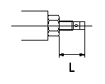
Temporary full load screw adjustment
Set the full load screw protrusion at L mm at assembly.
----------
L=14+-0.5mm
----------
L=14+-0.5mm
----------
L=14+-0.5mm
----------
L=14+-0.5mm
0000001901 CONTROL LEVER ANGLE
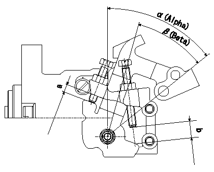
Lever angle alpha, beta
Dimensions a, b
----------
Alpha=50+-4deg Beta=37+-5deg a=(4.8~7.6)mm b=(11.8~16.4)mm
----------
Alpha=50+-4deg Beta=37+-5deg a=(4.8~7.6)mm b=(11.8~16.4)mm
----------
Alpha=50+-4deg Beta=37+-5deg a=(4.8~7.6)mm b=(11.8~16.4)mm
----------
Alpha=50+-4deg Beta=37+-5deg a=(4.8~7.6)mm b=(11.8~16.4)mm
Information:
Test Points (Voltages And Waveforms)
dc Voltages Conditions: 1. dc input voltage applied to POWER connector as shown.2. CALIBRATION CHECK/OPERATE switch in the OPERATE position.3. Neither transducer connected to indicator.4. TPI is reference for all voltages.Equipment Required: 6V3030 Digital Multimeterdc Input Voltages Waveforms Conditions: 1. dc power input voltage of 25 1 Volts.2. CALIBRATION CHECK/OPERATE switch in the CHECK position (can be held in CHECK position with tape).3. Neither transducer connected to indicator.4. TPI is reference for all waveforms.Equipment Required: dc oscilloscope (dual channel preferred). Waveform Time Relationships
VOLTAGES MAY VARY 10%, PULSE DURATIONS BY 20% EXCEPT 2.66 ms WHICH IS BASED ON A 12.000 kHz OSCILLATOR FREQ. (1C202). SIGNAL SOURCE IS INTERNAL CALIBRATOR. ALL TEST POINTS REFERENCED TO TP1.Waveform Time Relationships (enlarged scale)
VOLTAGES MAY VARY 10%, PULSE DURATIONS BY 20% EXCEPT 83.3 ?s AND 2.66 ms WHICH ARE EXACT BASED ON A 12.000 kHZ OSCILLATOR. (1C202) SIGNAL SOURCE IS INTERNAL CALIBRATOR. ALL TEST POINTS REFERENCED TO TP1.Disassembly Procedure
1 Remove six screws (1) from front panel (2), and remove panel (2) from case (3). Remove four screws (4) from the PC board, and also remove the locknuts from the two front panel switches (5) and (6). Carefully lift front panel (2) from PC (printed circuit) board (7).Calibration Procedure
To make sure the 6V3100 Timing Indicator Group (1) has good accuracy, check its calibration at a minimum of every six months. Also, the timing indicator will need calibration if: A. It does not show 2000 30 R/MIN at (A) and 32.0 .2 DEG at (B), when the CALIBRATION CHECK-OPERATE Switch (C) is in the CALIBRATION CHECK position. With no input signal at (D) or (E), the reading at R/MIN location (A) must show three zeros (000). If four zeros (0000) show, it is an indication of a possible need for calibration of the unit. This error only is not reason enough to do a complete calibration procedure. It is also not necessary to do a complete calibration procedure if the reading at the DEG location (B) has a decimal point as shown, (00.0) in addition to the three zeros.B. Reading is different than (000) at either location (A) or (B).All calibrations can be done with the use of a small screwdriver, a frequency counter and