Information injection-pump assembly
ZEXEL
104742-1162
1047421162
ISUZU
8943362312
8943362312

Rating:
Cross reference number
ZEXEL
104742-1162
1047421162
ISUZU
8943362312
8943362312
Zexel num
Bosch num
Firm num
Name
Calibration Data:
Adjustment conditions
Test oil
1404 Test oil ISO4113orSAEJ967d
1404 Test oil ISO4113orSAEJ967d
Test oil temperature
degC
45
45
50
Nozzle
105000-2010
Bosch type code
NP-DN12SD12TT
Nozzle holder
105780-2080
Opening pressure
MPa
14.7
14.7
15.19
Opening pressure
kgf/cm2
150
150
155
Injection pipe
Inside diameter - outside diameter - length (mm) mm 2-6-840
Inside diameter - outside diameter - length (mm) mm 2-6-840
Transfer pump pressure
kPa
20
20
20
Transfer pump pressure
kgf/cm2
0.2
0.2
0.2
Direction of rotation (viewed from drive side)
Right R
Right R
(Solenoid timer adjustment condition)
OFF
Injection timing adjustment
Pump speed
r/min
1050
1050
1050
Average injection quantity
mm3/st.
65.1
64.6
65.6
Difference in delivery
mm3/st.
4
Basic
*
Injection timing adjustment_02
Pump speed
r/min
2100
2100
2100
Average injection quantity
mm3/st.
21.4
17.9
24.9
Injection timing adjustment_03
Pump speed
r/min
1750
1750
1750
Average injection quantity
mm3/st.
65.3
59.8
70.8
Injection timing adjustment_04
Pump speed
r/min
1400
1400
1400
Average injection quantity
mm3/st.
63
59
67
Injection timing adjustment_05
Pump speed
r/min
1050
1050
1050
Average injection quantity
mm3/st.
65.1
64.1
66.1
Injection timing adjustment_06
Pump speed
r/min
700
700
700
Average injection quantity
mm3/st.
55.2
51.2
59.2
Injection timing adjustment_07
Pump speed
r/min
400
400
400
Average injection quantity
mm3/st.
65.3
60.3
70.3
Injection quantity adjustment
Pump speed
r/min
2100
2100
2100
Average injection quantity
mm3/st.
21.3
18.3
24.3
Difference in delivery
mm3/st.
7
Basic
*
Injection quantity adjustment_02
Pump speed
r/min
2200
2200
2200
Average injection quantity
mm3/st.
13
Governor adjustment
Pump speed
r/min
338
338
338
Average injection quantity
mm3/st.
9.4
7.4
11.4
Difference in delivery
mm3/st.
2
Basic
*
Governor adjustment_02
Pump speed
r/min
338
338
338
Average injection quantity
mm3/st.
9.4
7.4
11.4
Governor adjustment_03
Pump speed
r/min
450
450
450
Average injection quantity
mm3/st.
3
Timer adjustment
Pump speed
r/min
100
100
100
Average injection quantity
mm3/st.
100
80
120
Basic
*
Speed control lever angle
Pump speed
r/min
338
338
338
Average injection quantity
mm3/st.
0
0
0
Remarks
Magnet OFF
Magnet OFF
Speed control lever angle_02
Pump speed
r/min
100
100
100
Average injection quantity
mm3/st.
0
0
0
Remarks
Magnet OFF
Magnet OFF
0000000901
Pump speed
r/min
1600
1600
1600
Overflow quantity with S/T OFF
cm3/min
621
492
750
Stop lever angle
Pump speed
r/min
1600
1600
1600
Pressure
kPa
588.5
569
608
Pressure
kgf/cm2
6
5.8
6.2
Basic
*
Stop lever angle_02
Pump speed
r/min
1000
1000
1000
Pressure with S/T OFF
kPa
343.5
314
373
Pressure with S/T OFF
kgf/cm2
3.5
3.2
3.8
Stop lever angle_03
Pump speed
r/min
1600
1600
1600
Pressure with S/T OFF
kPa
588.5
569
608
Pressure with S/T OFF
kgf/cm2
6
5.8
6.2
Stop lever angle_04
Pump speed
r/min
1750
1750
1750
Pressure with S/T OFF
kPa
637.5
608
667
Pressure with S/T OFF
kgf/cm2
6.5
6.2
6.8
0000001101
Pump speed
r/min
1600
1600
1600
Timer stroke
mm
3
2.8
3.2
Basic
*
_02
Pump speed
r/min
850
850
850
Timer stroke with S/T ON
mm
0.5
0.5
_03
Pump speed
r/min
1450
1450
1450
Timer stroke with S/T OFF
mm
0.5
_04
Pump speed
r/min
1500
1500
1500
Timer stroke with S/T OFF
mm
0.9
0.3
1.5
_05
Pump speed
r/min
1600
1600
1600
Timer stroke with S/T OFF
mm
3
2.7
3.3
_06
Pump speed
r/min
1750
1750
1750
Timer stroke with S/T OFF
mm
5.7
5.3
6.1
0000001201
Max. applied voltage
V
16
16
16
Test voltage
V
25
24
26
Timing setting
K dimension
mm
3.1
3
3.2
KF dimension
mm
5.5
5.4
5.6
MS dimension
mm
0.9
0.8
1
Pre-stroke
mm
0.45
0.43
0.47
Control lever angle alpha
deg.
25
21
29
Control lever angle beta
deg.
36
31
41
Test data Ex:
0000001801 TEMP. ADJUST FULL-LOAD SCREW
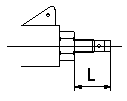
Temporary full load screw adjustment
Set the full load screw protrusion at L mm at assembly.
----------
L=14.0+-0.5mm
----------
L=14.0+-0.5mm
----------
L=14.0+-0.5mm
----------
L=14.0+-0.5mm
Information:
This instruction is written for electronic technicians only, and must not be used by service personnel with no training or knowledge of electronics. For repairs that can be done by the Caterpillar Dealer Serviceman, with no knowledge of electronics, see Special Instruction Form SMHS6964 "Using 1P3500 and 2P8280 Injection Timing Groups."As an aid to the technician for troubleshooting the inverter and timing light, the following information is given in this instruction:1. Circuit board illustrations showing the position of each of the components and the test points (T) for using a voltmeter or an oscilloscope.2. Schematics of the electrical circuit so the technician can easily follow the sequence of the circuit.3. Test point values.4. Electrical parts replacement information.5. Timing light calibration procedure.Timing Light
1P3500 And 2P8280 Timing Lights - Electrical Schematic, Test Points And Parts List
Inverter - Electrical Schematic, Test Points And Parts List
There is a two position switch that is marked ADV.-RPM on the side of the 1P3499 Timing Light. When the timing light is in use, operation of the ADV.-RPM switch is as follows:RPM Position
A fuel injection pulse opens the switch in the transducer and starts a positive pulse (TP9) of fixed duration, from the monostable composed of Q2 and Q3. This pulse turns on a transistor switch Q4, allowing current to pass through meter M1, which mechanically averages pulses from an operating engine, and is calibrated to read RPM. Switch S2 grounds the gate of SCR1 to prevent the flash tube from strobing.ADV. Position
A fuel injection pulse again starts a pulse from the monostable. Adjustment of R7, the TIME-ADVANCE control, now determines the pulse duration from the monostable. When R7 is adjusted so that TDC on the damper coincides with the pointer on the block of an operating engine, the monostable pulse duration is exactly the same as the fuel system advance measured in seconds. Transistor switch Q4 again turns on, allowing current to pass through meter M1, causing a meter indicator that is calibrated in degrees of advance instead of seconds.Electrical Calibration Procedure
Before the electrical calibration can be done, the following equipment must be obtained.1) Oscilloscope with triggered sweep. Heath Co. M/N SO-4530 or equivalent.2) Signal generator. Heath M/N SG-72A or equivalent.3) Electronic counter. Data Precision M/N 5740 or equivalent.4) Electronic switch (dealer built).Calibration Procedure
(1) Hold the 1P3499 Timing Light in the same position (about a 45° angle) as if measuring the timing advance on an engine, and check the mechanical meter zero. Make an adjustment to zero if necessary. (2) To remove the protective rubber boot from the flash tube, twist the rubber boot and pull it away from the timing light as shown. (3) Remove the right side (side that has the serial number tag) of the timing light case.(4) Connect the 1P3499 Timing Light to a circuit like the one that follows. This will simulate (be the same as) a fuel flow transducer on an engine that is operating at 2400 RPM. (5) Turn the TIME-ADV. control counterclockwise (CCW) to its minimum