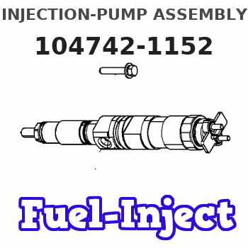
Information injection-pump assembly
ZEXEL
104742-1152
1047421152
ISUZU
8943368282
8943368282
Rating:
Cross reference number
ZEXEL
104742-1152
1047421152
ISUZU
8943368282
8943368282
Zexel num
Bosch num
Firm num
Name
Calibration Data:
Adjustment conditions
Test oil
1404 Test oil ISO4113orSAEJ967d
1404 Test oil ISO4113orSAEJ967d
Test oil temperature
degC
45
45
50
Nozzle
105780-0060
Bosch type code
NP-DN0SD1510
Nozzle holder
105780-2150
Opening pressure
MPa
13
13
13.3
Opening pressure
kgf/cm2
133
133
136
Injection pipe
157805-7320
Injection pipe
Inside diameter - outside diameter - length (mm) mm 2-6-450
Inside diameter - outside diameter - length (mm) mm 2-6-450
Joint assembly
157641-4720
Tube assembly
157641-4020
Transfer pump pressure
kPa
20
20
20
Transfer pump pressure
kgf/cm2
0.2
0.2
0.2
Direction of rotation (viewed from drive side)
Right R
Right R
Injection timing adjustment
Pump speed
r/min
1050
1050
1050
Average injection quantity
mm3/st.
64.4
63.9
64.9
Difference in delivery
mm3/st.
4
Basic
*
Injection timing adjustment_02
Pump speed
r/min
2100
2100
2100
Average injection quantity
mm3/st.
13.5
10
17
Injection timing adjustment_03
Pump speed
r/min
1750
1750
1750
Average injection quantity
mm3/st.
61.7
56.2
67.2
Injection timing adjustment_04
Pump speed
r/min
1400
1400
1400
Average injection quantity
mm3/st.
64.1
60.1
68.1
Injection timing adjustment_05
Pump speed
r/min
1050
1050
1050
Average injection quantity
mm3/st.
64.4
63.4
65.4
Injection timing adjustment_06
Pump speed
r/min
700
700
700
Average injection quantity
mm3/st.
54.5
50.5
58.5
Injection timing adjustment_07
Pump speed
r/min
400
400
400
Average injection quantity
mm3/st.
64.7
59.7
69.7
Injection quantity adjustment
Pump speed
r/min
2100
2100
2100
Average injection quantity
mm3/st.
13.5
10.5
16.5
Difference in delivery
mm3/st.
7
Basic
*
Injection quantity adjustment_02
Pump speed
r/min
2200
2200
2200
Average injection quantity
mm3/st.
8
Governor adjustment
Pump speed
r/min
350
350
350
Average injection quantity
mm3/st.
9.4
7.4
11.4
Difference in delivery
mm3/st.
2
Basic
*
Governor adjustment_02
Pump speed
r/min
350
350
350
Average injection quantity
mm3/st.
9.4
7.4
11.4
Governor adjustment_03
Pump speed
r/min
450
450
450
Average injection quantity
mm3/st.
3
Timer adjustment
Pump speed
r/min
100
100
100
Average injection quantity
mm3/st.
100
80
120
Basic
*
Speed control lever angle
Pump speed
r/min
350
350
350
Average injection quantity
mm3/st.
0
0
0
Remarks
Magnet OFF
Magnet OFF
Speed control lever angle_02
Pump speed
r/min
100
100
100
Average injection quantity
mm3/st.
0
0
0
Remarks
Magnet OFF
Magnet OFF
0000000901
Pump speed
r/min
1600
1600
1600
Overflow quantity
cm3/min
621
492
750
Stop lever angle
Pump speed
r/min
1600
1600
1600
Pressure with S/T OFF
kPa
588.5
569
608
Pressure with S/T OFF
kgf/cm2
6
5.8
6.2
Basic
*
Stop lever angle_02
Pump speed
r/min
1000
1000
1000
Pressure with S/T OFF
kPa
343.5
314
373
Pressure with S/T OFF
kgf/cm2
3.5
3.2
3.8
Stop lever angle_03
Pump speed
r/min
1600
1600
1600
Pressure with S/T OFF
kPa
588.5
569
608
Pressure with S/T OFF
kgf/cm2
6
5.8
6.2
Stop lever angle_04
Pump speed
r/min
1750
1750
1750
Pressure with S/T OFF
kPa
637.5
608
667
Pressure with S/T OFF
kgf/cm2
6.5
6.2
6.8
0000001101
Pump speed
r/min
1600
1600
1600
Timer stroke with S/T OFF
mm
3
2.8
3.2
Basic
*
_02
Pump speed
r/min
750
650
850
Timer stroke with S/T ON
mm
0.5
0.5
0.5
_03
Pump speed
r/min
1450
1450
1450
Timer stroke with S/T OFF
mm
0.5
_04
Pump speed
r/min
1500
1500
1500
Timer stroke with S/T OFF
mm
0.95
0.3
1.6
_05
Pump speed
r/min
1600
1600
1600
Timer stroke with S/T OFF
mm
3
2.7
3.3
_06
Pump speed
r/min
1750
1750
1750
Timer stroke with S/T OFF
mm
5.7
5.3
6.1
0000001201
Max. applied voltage
V
16
16
16
Test voltage
V
25
24
26
Timing setting
K dimension
mm
3.1
3
3.2
KF dimension
mm
5.5
5.4
5.6
MS dimension
mm
0.9
0.8
1
Pre-stroke
mm
0.45
0.43
0.47
Control lever angle alpha
deg.
25
21
29
Control lever angle beta
deg.
35
30
40
Test data Ex:
0000001801 V-FICD ADJUSTMENT
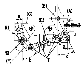
Rod length adjustment
With the control lever at the idle position (contacting the idle stopper bolt), adjust the length so that the link lever and link bracket aligning marks are aligned, then fix.
Adjustment of the V-FICD
Adjust so that the distance between the control lever pin and the V-FICD rod is S.
(A) = idle stopper bolt
(B) = control lever
(C) = link bracket
(D) = aligning mark
(E) = rod
(F) = link lever
----------
S=1+1mm
----------
a=15deg b=(45)deg c=25+-4deg T=3.5~5N-m(0.35~0.5kgf-m) S=1+1mm R1=R32 R2=R28
----------
S=1+1mm
----------
a=15deg b=(45)deg c=25+-4deg T=3.5~5N-m(0.35~0.5kgf-m) S=1+1mm R1=R32 R2=R28
Information:
Delco-Remy Alternator
(1) Regulator. (2) Roller bearing. (3) Stator winding. (4) Ball bearing. (5) Rectifier bridge. (6) Field winding. (7) Rotor assembly. (8) Fan.Alternator (Bosch)
The alternator is driven by V-belts from the crankshaft pulley. This alternator is a three phase, self-rectifying charging unit. The regulator is part of the alternator.
Bosch Alternator
(1) Fan. (2) Stator winding. (3) Field winding. (4) Regulator. (5) Ball bearing. (6) Roller bearing. (7) Rotor. (8) Rectifier assembly.This alternator design has no need for slip rings or brushes, and the only part that has movement is the rotor assembly. All conductors that carry current are stationary. The conductors are: the field winding, stator windings, six rectifying diodes, and the regulator circuit components.The rotor assembly has many magnetic poles like fingers with air space between each opposite pole. The poles have residual magnetism (like permanent magnets) that produce a small amount of magnet-like lines of force (magnetic field) between the poles. As the rotor assembly begins to turn between the field winding and the stator windings, a small amount of alternating current (AC) is produced in the stator windings from the small magnetic lines of force made by the residual magnetism of the poles. This AC current is changed to direct current (DC) when it passes through the diodes of the rectifier bridge. Most of this current goes to charge the battery and to supply the low amperage circuit, and the remainder is sent to the field windings. The DC current flow through the field windings (wires around an iron core) now increases the strength of the magnetic lines of force. These stronger lines of force now increase the amount of AC current produced in the stator windings. The increased speed of the rotor assembly also increases the current and voltage output of the alternator.The voltage regulator is a solid state (transistor, stationary parts) electronic switch. It feels the voltage in the system and switches on and off many times a second to control the field current (DC current to the field windings) for the alternator to make the needed voltage output.Alternator (Nippondenso)
The alternator is driven by a V-belt from the crankshaft pulley. The only part in the alternator which has movement is rotor assembly (9). Rotor assembly (9) is held in position by a ball bearing at each end of rotor shaft (8).The alternator is made up of a frame (3) on the drive end, rotor assembly (9), stator assembly (5), rectifier assembly (11), brushes (7) and holder assembly, slip rings (13), rear end frame (12) and regulator (6). Drive pulley (1) has a fan (2) for heat removal by the movement of air through the alternator.
Alternator Schematic (With Regulator Attached)
(1) Pulley. (2) Fan. (3) Drive end frame. (4) Stator coils. (5) Stator assembly. (6) Regulator. (7) Brushes. (8) Rotor shaft. (9) Rotor assembly. (10) Field windings. (11) Rectifier assembly. (12) Rear end frame. (13) Slip rings.Rotor assembly (9) has field windings (10) (wires around an iron core) which make magnetic lines of force when direct