Information injection-pump assembly
ZEXEL
104742-1100
1047421100
ISUZU
8944789390
8944789390

Rating:
Cross reference number
ZEXEL
104742-1100
1047421100
ISUZU
8944789390
8944789390
Zexel num
Bosch num
Firm num
Name
Calibration Data:
Adjustment conditions
Test oil
1404 Test oil ISO4113orSAEJ967d
1404 Test oil ISO4113orSAEJ967d
Test oil temperature
degC
45
45
50
Nozzle
105000-2010
Bosch type code
NP-DN12SD12TT
Nozzle holder
105780-2080
Opening pressure
MPa
14.7
14.7
15.19
Opening pressure
kgf/cm2
150
150
155
Injection pipe
Inside diameter - outside diameter - length (mm) mm 2-6-840
Inside diameter - outside diameter - length (mm) mm 2-6-840
Transfer pump pressure
kPa
20
20
20
Transfer pump pressure
kgf/cm2
0.2
0.2
0.2
Direction of rotation (viewed from drive side)
Right R
Right R
(Solenoid timer adjustment condition)
OFF
Injection timing adjustment
Pump speed
r/min
1050
1050
1050
Average injection quantity
mm3/st.
64.4
63.9
64.9
Difference in delivery
mm3/st.
4
Basic
*
Injection timing adjustment_02
Pump speed
r/min
2100
2100
2100
Average injection quantity
mm3/st.
13.5
10
17
Injection timing adjustment_03
Pump speed
r/min
1750
1750
1750
Average injection quantity
mm3/st.
61.7
56.2
67.2
Injection timing adjustment_04
Pump speed
r/min
1400
1400
1400
Average injection quantity
mm3/st.
64.1
60.1
68.1
Injection timing adjustment_05
Pump speed
r/min
1050
1050
1050
Average injection quantity
mm3/st.
64.4
63.4
65.4
Injection timing adjustment_06
Pump speed
r/min
700
700
700
Average injection quantity
mm3/st.
54.5
50.5
58.5
Injection timing adjustment_07
Pump speed
r/min
400
400
400
Average injection quantity
mm3/st.
64.7
59.7
69.7
Injection quantity adjustment
Pump speed
r/min
2100
2100
2100
Average injection quantity
mm3/st.
13.5
10.5
16.5
Difference in delivery
mm3/st.
7
Basic
*
Injection quantity adjustment_02
Pump speed
r/min
2200
2200
2200
Average injection quantity
mm3/st.
8
Governor adjustment
Pump speed
r/min
350
350
350
Average injection quantity
mm3/st.
9.4
7.4
11.4
Difference in delivery
mm3/st.
2
Basic
*
Governor adjustment_02
Pump speed
r/min
350
350
350
Average injection quantity
mm3/st.
9.4
7.4
11.4
Governor adjustment_03
Pump speed
r/min
450
450
450
Average injection quantity
mm3/st.
3
Timer adjustment
Pump speed
r/min
100
100
100
Average injection quantity
mm3/st.
100
80
120
Basic
*
Speed control lever angle
Pump speed
r/min
350
350
350
Average injection quantity
mm3/st.
0
0
0
Remarks
Magnet OFF
Magnet OFF
Speed control lever angle_02
Pump speed
r/min
100
100
100
Average injection quantity
mm3/st.
0
0
0
Remarks
Magnet OFF
Magnet OFF
0000000901
Pump speed
r/min
1600
1600
1600
Overflow quantity with S/T OFF
cm3/min
621
492
750
Stop lever angle
Pump speed
r/min
1600
1600
1600
Pressure with S/T OFF
kPa
588.5
569
608
Pressure with S/T OFF
kgf/cm2
6
5.8
6.2
Basic
*
Stop lever angle_02
Pump speed
r/min
800
800
800
Pressure with S/T ON
kPa
657
608
706
Pressure with S/T ON
kgf/cm2
6.7
6.2
7.2
Stop lever angle_03
Pump speed
r/min
1600
1600
1600
Pressure with S/T OFF
kPa
588.5
569
608
Pressure with S/T OFF
kgf/cm2
6
5.8
6.2
Stop lever angle_04
Pump speed
r/min
1750
1750
1750
Pressure with S/T OFF
kPa
637.5
608
667
Pressure with S/T OFF
kgf/cm2
6.5
6.2
6.8
0000001101
Pump speed
r/min
1600
1600
1600
Timer stroke with S/T OFF
mm
3
2.8
3.2
Basic
*
_02
Pump speed
r/min
750
650
850
Timer stroke with S/T ON
mm
0.5
0.5
0.5
_03
Pump speed
r/min
1500
1500
1500
Timer stroke with S/T OFF
mm
0.85
0.5
1.2
_04
Pump speed
r/min
1600
1600
1600
Timer stroke with S/T OFF
mm
3
2.7
3.3
_05
Pump speed
r/min
1750
1750
1750
Timer stroke with S/T OFF
mm
5.7
5.3
6.1
0000001201
Max. applied voltage
V
16
16
16
Test voltage
V
25
24
26
Timing setting
K dimension
mm
3.1
3.1
3.1
KF dimension
mm
5.5
5.4
5.6
MS dimension
mm
0.9
0.8
1
Pre-stroke
mm
0.45
0.43
0.47
Control lever angle alpha
deg.
25
21
29
Control lever angle beta
deg.
35
30
40
Test data Ex:
0000001801 TEMP. ADJUST FULL-LOAD SCREW
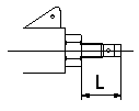
Temporary full load screw adjustment
Set the full load screw protrusion at L mm at assembly.
----------
L=14.0+-0.5mm
----------
L=14.0+-0.5mm
----------
L=14.0+-0.5mm
----------
L=14.0+-0.5mm
0000001901 V-FICD ADJUSTMENT
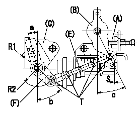
Rod length adjustment
With the control lever at the idle position (contacting the idle stopper bolt), adjust the length so that the link lever and link bracket aligning marks are aligned, then fix.
Adjustment of the V-FICD
Adjust so that the distance between the control lever pin and the V-FICD rod is S.
(A) = idle stopper bolt
(B) = control lever
(C) = link bracket
(D) = aligning mark
(E) = rod
(F) = link lever
----------
S=1+1mm
----------
a=15deg b=(45)deg c=25+-4deg T=3.5~5N-m(0.35~0.5kgf-m) S=1+1mm R1=R32 R2=R28
----------
S=1+1mm
----------
a=15deg b=(45)deg c=25+-4deg T=3.5~5N-m(0.35~0.5kgf-m) S=1+1mm R1=R32 R2=R28
Information:
Jacket Water Pump
A failed water pump might cause severe engine overheating problems that could result in cracks in the cylinder head, a piston seizure or other potential damage to the engine.Visually inspect the water pump for leaks. If leaking is observed, replace all seals. Refer to the Service Manual for the procedure to replace the seals.Turbocharger
Refer to the Turbocharger topic in the Every 3000 Hours maintenance interval for information regarding turbocharger inspection. Refer to the Service Manual, or consult with your Caterpillar dealer for the complete turbocharger inspection procedure.Alternator and Starting Motor
Caterpillar recommends a scheduled inspection of the alternator. Inspect the alternator for loose connections and proper battery charging. Inspect the ammeter gauge during engine operation to ensure the batteries and/or electrical system is performing correctly. Make repairs as necessary. Refer to the Service Manual.Check the alternator and battery charger for proper operation. If the batteries are properly charged, ammeter reading should be very near zero. All batteries should be kept charged. The batteries should be kept warm because temperature affects the cranking power. If the battery is too cold, it will not crank the engine, even if the engine is warm.When the engine is not run for long periods of time or run for short periods, the batteries may not fully recharge. Ensure the alternator performs properly to charge the battery and to help prevent the battery from freezing.If the starting motor fails, the engine may not start in an emergency situation. Caterpillar recommends a schedule inspection/check of your starting motor. The starting motor should be checked for correct operation. All electrical connections should be cleaned and checked. Refer to the established procedure for inspection and specifications in the Service Manual, or contact your Caterpillar dealer for assistance.Repair Before Failure
Until recently, engine maintenance and repair management involved changing the oil when it was convenient and repairing the engine when it was damaged. This seemed to be the accepted way of managing a maintenance operation.However, due to a variety of circumstances, increasing competition have caused users to look for ways to prolong equipment life and lower operating costs so that they could be competitive.To assist Caterpillar engine users in prolonging engine life and reducing operating costs, the Value Planned Repair approach to engine maintenance was developed.The Value Planned Repair approach can be tailored for any engine. This approach, when properly structured, outlines every maintenance and repair service required to support an engine from the day it enters service until the day it is retired.To ensure the repair is performed efficiently and expediently, the Value Planned Repair concept approaches a given repair in three basis steps:1. Repair determination2. Evaluation of repair options3. Selection of the most appropriate optionThe Value Planned Repair approach addresses:* Services required to maintain an engine at optimum efficiency.* Scheduled maintenance, repairs and overhauls to minimize unscheduled downtime.* Preplanned repairs and overhauls that can be flat-rated, putting you in charge of costs.* Repair