Information injection-pump assembly
ZEXEL
104742-1091
1047421091
ISUZU
8943177261
8943177261

Rating:
Cross reference number
ZEXEL
104742-1091
1047421091
ISUZU
8943177261
8943177261
Zexel num
Bosch num
Firm num
Name
Calibration Data:
Adjustment conditions
Test oil
1404 Test oil ISO4113orSAEJ967d
1404 Test oil ISO4113orSAEJ967d
Test oil temperature
degC
45
45
50
Nozzle
105000-2010
Bosch type code
NP-DN12SD12TT
Nozzle holder
105780-2080
Opening pressure
MPa
14.7
14.7
15.19
Opening pressure
kgf/cm2
150
150
155
Injection pipe
Inside diameter - outside diameter - length (mm) mm 2-6-840
Inside diameter - outside diameter - length (mm) mm 2-6-840
Transfer pump pressure
kPa
20
20
20
Transfer pump pressure
kgf/cm2
0.2
0.2
0.2
Direction of rotation (viewed from drive side)
Right R
Right R
(Solenoid timer adjustment condition)
OFF
Injection timing adjustment
Pump speed
r/min
1050
1050
1050
Average injection quantity
mm3/st.
65.1
64.6
65.6
Difference in delivery
mm3/st.
4
Basic
*
Injection timing adjustment_02
Pump speed
r/min
2100
2100
2100
Average injection quantity
mm3/st.
21.4
17.9
24.9
Injection timing adjustment_03
Pump speed
r/min
1750
1750
1750
Average injection quantity
mm3/st.
65.3
59.8
70.8
Injection timing adjustment_04
Pump speed
r/min
1400
1400
1400
Average injection quantity
mm3/st.
63
59
67
Injection timing adjustment_05
Pump speed
r/min
1050
1050
1050
Average injection quantity
mm3/st.
65.1
64.1
66.1
Injection timing adjustment_06
Pump speed
r/min
700
700
700
Average injection quantity
mm3/st.
55.2
51.2
59.2
Injection timing adjustment_07
Pump speed
r/min
400
400
400
Average injection quantity
mm3/st.
65.3
60.3
70.3
Injection quantity adjustment
Pump speed
r/min
2100
2100
2100
Average injection quantity
mm3/st.
21.3
18.3
24.3
Difference in delivery
mm3/st.
7
Basic
*
Injection quantity adjustment_02
Pump speed
r/min
2200
2200
2200
Average injection quantity
mm3/st.
13
Governor adjustment
Pump speed
r/min
338
338
338
Average injection quantity
mm3/st.
9.4
7.4
11.4
Difference in delivery
mm3/st.
2
Basic
*
Governor adjustment_02
Pump speed
r/min
338
338
338
Average injection quantity
mm3/st.
9.4
7.4
11.4
Governor adjustment_03
Pump speed
r/min
450
450
450
Average injection quantity
mm3/st.
3
Timer adjustment
Pump speed
r/min
100
100
100
Average injection quantity
mm3/st.
100
80
120
Basic
*
Speed control lever angle
Pump speed
r/min
338
338
338
Average injection quantity
mm3/st.
0
0
0
Remarks
Magnet OFF
Magnet OFF
Speed control lever angle_02
Pump speed
r/min
100
100
100
Average injection quantity
mm3/st.
0
0
0
Remarks
Magnet OFF
Magnet OFF
0000000901
Pump speed
r/min
1600
1600
1600
Overflow quantity with S/T OFF
cm3/min
621
492
750
Stop lever angle
Pump speed
r/min
1600
1600
1600
Pressure
kPa
588.5
569
608
Pressure
kgf/cm2
6
5.8
6.2
Basic
*
Stop lever angle_02
Pump speed
r/min
1000
1000
1000
Pressure with S/T OFF
kPa
343.5
314
373
Pressure with S/T OFF
kgf/cm2
3.5
3.2
3.8
Stop lever angle_03
Pump speed
r/min
1600
1600
1600
Pressure with S/T OFF
kPa
588.5
569
608
Pressure with S/T OFF
kgf/cm2
6
5.8
6.2
Stop lever angle_04
Pump speed
r/min
1750
1750
1750
Pressure with S/T OFF
kPa
637.5
608
667
Pressure with S/T OFF
kgf/cm2
6.5
6.2
6.8
0000001101
Pump speed
r/min
1600
1600
1600
Timer stroke with S/T OFF
mm
3
2.8
3.2
Basic
*
_02
Pump speed
r/min
850
850
850
Timer stroke with S/T ON
mm
0.5
0.5
_03
Pump speed
r/min
1450
1450
1450
Timer stroke with S/T OFF
mm
0.5
_04
Pump speed
r/min
1500
1500
1500
Timer stroke with S/T OFF
mm
0.9
0.3
1.5
_05
Pump speed
r/min
1600
1600
1600
Timer stroke with S/T OFF
mm
3
2.7
3.3
_06
Pump speed
r/min
1750
1750
1750
Timer stroke with S/T OFF
mm
5.7
5.3
6.1
0000001201
Max. applied voltage
V
16
16
16
Test voltage
V
25
24
26
Timing setting
K dimension
mm
3.1
3
3.2
KF dimension
mm
5.5
5.4
5.6
MS dimension
mm
0.9
0.8
1
Pre-stroke
mm
0.45
0.43
0.47
Control lever angle alpha
deg.
25
21
29
Control lever angle beta
deg.
36
31
41
Test data Ex:
0000001801 MOTOR LEVER ADJUSTMENT

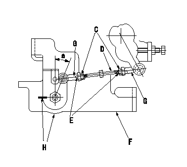
Motor lever adjustment
With the control lever contacting the idle stopper bolt, adjust the length of the rod so that the stepping motor bracket and the motor lever position alignment stamping are aligned.
Nut tightening torque: T1
After confirming the specified torque, apply yellow paint to the end of the rod and the nut.
C = nut
D = rod
E = yellow paint
F = stepping motor bracket
G = end of rod
H = angle alignment stamping
----------
T1=3.4~4.9N-m(0.35~0.5kgf-m)
----------
a=(25)deg
----------
T1=3.4~4.9N-m(0.35~0.5kgf-m)
----------
a=(25)deg
0000001901 MICROSWITCH ADJUSTMENT

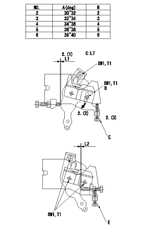
Microswitch adjustment
1. Adjusting plate selection
Select a plate from the lever angle beta in the table and then fix the lever.
2. Full position adjustment
(1)Insert a shim (L2) between the control lever and the full stopper bolt.
(2)Move the microswitch in the direction of the arrow and confirm that it turns ON.
(3)Screw in bolt 1 and fix the microswitch when it turns from ON to OFF.
3. Idle position confirmation
(1)With a shim L2 = L3 inserted between the control lever and the idle stopper bolt, confirm that the microswitch is ON.
If it is OFF, exchange the installed plate with a plate with a higher number and readjust from full position in 2.
(2)Then insert a shim L2 = L4 and confirm that the microswitch is OFF.
If it is ON, exchange the installed plate with a plate with a lower number and readjust from full position in 2.
(3)Remove bolt 1 after confirming that On/Off positions at (1) and (2) are within the specifications
After confirming the specified torque of the bolt shown in figure 3, apply yellow paint.
Caution 1:Use the unit to confirm (1) and (2) above and insert a shim L5 when the lever is moved from idle in the full direction.
When the number of steps exceeds S1 in Caution (1) and (2) in the ON and OFF positions at clearance L2 = L6, install a plate with a number 2 ranks up or down from the plate that is already installed.
Caution 3: When applying yellow paint to the cam plate, do not apply paint to the cam face or the outside of the microswitch roller.
A = angle beta
B = plate stamping
C = inspection standard L7
D = microswitch fixing bolt
E = bolt 1
----------
L1=0.8mm L3=1.80mm L4=1.00mm L5=1.00~1.90mm L6=0.8mm L7=0.70~0.80mm
----------
L1=0.8mm L7=0.70~0.80mm SW1=SW7mm T1=2.0~2.9N-m{0.2~0.3kgf-m}
----------
L1=0.8mm L3=1.80mm L4=1.00mm L5=1.00~1.90mm L6=0.8mm L7=0.70~0.80mm
----------
L1=0.8mm L7=0.70~0.80mm SW1=SW7mm T1=2.0~2.9N-m{0.2~0.3kgf-m}
Information:
Heavy Duty Air Cleaners
Generator set engines equipped with heavy duty air cleaners have a serviceable air cleaner element. The element may be cleaned up to six times, but must be replaced Every Year.Remove and Install Air Cleaner Elements
Heavy duty air cleaner:(1) service indicator(2) upper body (air filter element housing)(3) clamps(4) lower body (tube element)(5) dust collector cup1. Loosen clamps (3) between the lower body (4) and the dust collector cup (5). Remove the cup.2. Loosen the clamps between the lower body and the upper body (2). Remove the tube element.3. Clean the tubes from both sides with water or air.4. Remove the air filter element from the upper body (2). Wipe the inside of the upper body clean.5. Inspect and clean air filter element. Install a clean or new element.6. Inspect the gasket between the upper body and lower body. Inspect the seal between the lower body and the dust collector cup. Install a new gasket and seal if necessary.7. Install the cleaned, dry tube element. Tighten the retaining clamps attaching the lower body to the upper body.8. Wipe the dust collector cup clean. Install the cup and tighten the retaining clamps.9. Reset the service indicator (1).Cleaning Air Filter Elements
The primary element (Caterpillar air filters) can be cleaned several times before replacement. The element, when cleaned, should be thoroughly checked for rips or tears in the filter material.Replace the primary element at least EVERY YEAR regardless of operating hours it has accumulated.
Do not clean filter elements by bumping or tapping.Do not use filter elements with damaged pleats, gaskets or seals. Engine damage could result.
Filter elements can be cleaned with air pressure, 205 kPa (30 psi) maximum, or water pressure, 280 kPa (40 psi) maximum, or detergent washing. Have spare elements on hand to use while cleaning used elements.* Direct air or water along the length of the plate inside and outside of air filter element.The element can be washed in warm water and nonsudsing household detergent, such as automatic dishwasher detergent. Rinse inside and outside the pleats. The filter should then be thoroughly air dried and inspected.* Inspect the filter elements after cleaning for any rips, tears or damage. Insert a light inside of the clean, dry element. Do not use a filter element with damaged pleats, gaskets or seals. Discard the element if damaged.* Wrap and store the clean filter elements in a clean, dry place.* Reset the service indicator by pushing the piston plunger in.For more information on air cleaner element cleaning, refer to Guideline for Reusable Parts-Cleaning and Inspection of Air Filters, SEBU8062.Air Starter & Air Tank (If Equipped)
Check Lubricator Level
Never allow the lubricator bowl (if equipped) to become empty. The starting motor will be damaged by lack of proper lubrication.
The vanes of the starting motor are lubricated with a fine mist of oil from the motor lubricator. Check the level of oil in the lubricator bowl. If the bowl is less than half full, add lubricant. Use non detergent 10W engine oil for temperatures