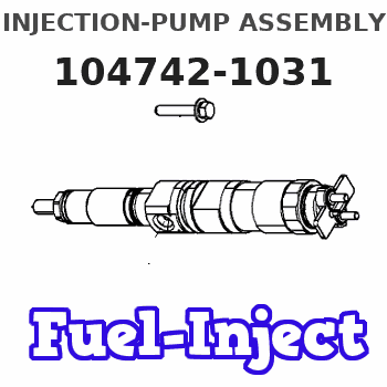
Information injection-pump assembly
ZEXEL
104742-1031
1047421031
ISUZU
8944046181
8944046181
Rating:
Cross reference number
ZEXEL
104742-1031
1047421031
ISUZU
8944046181
8944046181
Zexel num
Bosch num
Firm num
Name
104742-1031
8944046181 ISUZU
INJECTION-PUMP ASSEMBLY
4BE1F *
4BE1F *
Calibration Data:
Adjustment conditions
Test oil
1404 Test oil ISO4113orSAEJ967d
1404 Test oil ISO4113orSAEJ967d
Test oil temperature
degC
45
45
50
Nozzle
105000-2010
Bosch type code
NP-DN12SD12TT
Nozzle holder
105780-2080
Opening pressure
MPa
14.7
14.7
15.19
Opening pressure
kgf/cm2
150
150
155
Injection pipe
Inside diameter - outside diameter - length (mm) mm 2-6-840
Inside diameter - outside diameter - length (mm) mm 2-6-840
Transfer pump pressure
kPa
20
20
20
Transfer pump pressure
kgf/cm2
0.2
0.2
0.2
Direction of rotation (viewed from drive side)
Right R
Right R
Injection timing adjustment
Pump speed
r/min
1050
1050
1050
Average injection quantity
mm3/st.
65.4
64.9
65.9
Difference in delivery
mm3/st.
4
Basic
*
Oil temperature
degC
50
48
52
Injection timing adjustment_02
Pump speed
r/min
400
400
400
Average injection quantity
mm3/st.
65.4
60.9
69.9
Oil temperature
degC
48
46
50
Injection timing adjustment_03
Pump speed
r/min
700
700
700
Average injection quantity
mm3/st.
56.8
53.3
60.3
Oil temperature
degC
50
48
52
Injection timing adjustment_04
Pump speed
r/min
1050
1050
1050
Average injection quantity
mm3/st.
65.4
64.4
66.4
Difference in delivery
mm3/st.
4
Basic
*
Oil temperature
degC
50
48
52
Injection timing adjustment_05
Pump speed
r/min
1400
1400
1400
Average injection quantity
mm3/st.
65.5
61.5
69.5
Oil temperature
degC
50
48
52
Injection timing adjustment_06
Pump speed
r/min
1750
1750
1750
Average injection quantity
mm3/st.
66
60.5
71.5
Difference in delivery
mm3/st.
6
Oil temperature
degC
50
48
52
Injection quantity adjustment
Pump speed
r/min
1900
1900
1900
Average injection quantity
mm3/st.
16.6
13.6
19.6
Difference in delivery
mm3/st.
7
Basic
*
Oil temperature
degC
50
48
52
Injection quantity adjustment_02
Pump speed
r/min
2000
2000
2000
Average injection quantity
mm3/st.
8
Oil temperature
degC
50
48
52
Injection quantity adjustment_03
Pump speed
r/min
1900
1900
1900
Average injection quantity
mm3/st.
16.6
13.6
19.6
Difference in delivery
mm3/st.
7
Oil temperature
degC
50
48
52
Governor adjustment
Pump speed
r/min
350
350
350
Average injection quantity
mm3/st.
8.5
6.5
10.5
Difference in delivery
mm3/st.
2
Basic
*
Oil temperature
degC
48
46
50
Governor adjustment_02
Pump speed
r/min
350
350
350
Average injection quantity
mm3/st.
8.5
6.5
10.5
Difference in delivery
mm3/st.
2
Oil temperature
degC
48
46
50
Timer adjustment
Pump speed
r/min
100
100
100
Average injection quantity
mm3/st.
80
80
120
Basic
*
Oil temperature
degC
48
46
50
Remarks
Full
Full
Timer adjustment_02
Pump speed
r/min
100
100
100
Average injection quantity
mm3/st.
80
80
Oil temperature
degC
48
46
50
Speed control lever angle
Pump speed
r/min
350
350
350
Average injection quantity
mm3/st.
0
0
0
Oil temperature
degC
48
46
50
Remarks
Magnet OFF at idling position
Magnet OFF at idling position
Speed control lever angle_02
Pump speed
r/min
100
100
100
Average injection quantity
mm3/st.
0
0
0
Oil temperature
degC
48
46
50
Remarks
Magnet OFF at idling position
Magnet OFF at idling position
0000000901
Pump speed
r/min
1600
1600
1600
Overflow quantity
cm3/min
620
490
750
Oil temperature
degC
50
48
52
Stop lever angle
Pump speed
r/min
1600
1600
1600
Pressure with S/T OFF
kPa
588
568
608
Pressure with S/T OFF
kgf/cm2
6
5.8
6.2
Basic
*
Oil temperature
degC
50
48
52
Stop lever angle_02
Pump speed
r/min
1600
1600
1600
Pressure with S/T OFF
kPa
588
568
608
Pressure with S/T OFF
kgf/cm2
6
5.8
6.2
Basic
*
Oil temperature
degC
50
48
52
Stop lever angle_03
Pump speed
r/min
1750
1750
1750
Pressure with S/T OFF
kPa
637
608
666
Pressure with S/T OFF
kgf/cm2
6.5
6.2
6.8
Oil temperature
degC
50
48
52
0000001101
Pump speed
r/min
1600
1600
1600
Timer stroke with S/T OFF
mm
3
2.8
3.2
Basic
*
Oil temperature
degC
50
48
52
_02
Pump speed
r/min
750
650
850
Timer stroke with S/T ON
mm
0.5
0.5
0.5
Oil temperature
degC
50
48
52
_03
Pump speed
r/min
1450
1450
1450
Timer stroke with S/T OFF
mm
0.5
Oil temperature
degC
50
48
52
_04
Pump speed
r/min
1500
1500
1500
Timer stroke with S/T OFF
mm
0.9
0.5
1.2
Oil temperature
degC
50
48
52
_05
Pump speed
r/min
1600
1600
1600
Timer stroke with S/T OFF
mm
3
2.8
3.2
Basic
*
Oil temperature
degC
50
48
52
_06
Pump speed
r/min
1750
1750
1750
Timer stroke with S/T OFF
mm
5.7
5.4
6.1
Oil temperature
degC
50
48
52
0000001201
Max. applied voltage
V
16
16
16
Test voltage
V
25
24
26
Timing setting
K dimension
mm
3.1
3
3.2
KF dimension
mm
5.5
5.4
5.6
MS dimension
mm
0.9
0.8
1
Pre-stroke
mm
0.45
0.43
0.47
Control lever angle alpha
deg.
50
46
54
Control lever angle beta
deg.
37
32
42
Test data Ex:
0000001801 Temp. adjust full-load screw
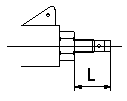
Temporary full load screw adjustment
Set the full load screw protrusion at L mm at assembly.
----------
L=14.0+-0.5mm
----------
L=14.0+-0.5mm
----------
L=14.0+-0.5mm
----------
L=14.0+-0.5mm
Information:
Test
Set up as illustrated and turn the alternator to measure vacuum pump performance. If the measurement is lower than nominal values, disassemble and check for broken vane, traces of interference on housing, rotor and plate surfaces. Replace if defective.Ultimate vacuum Exhaust characteristics after 20 seconds 4.9 Safety Relay
(1) R8T30171 Safety Relay Inspection Measure voltage at each terminal in the sequence shown below to identify faulty parts.(a) On-vehicle Test (b) Component TestThe resistance value between terminals "R" and "L" shall be within specified range.(2) Inspection by RX-Q30 Safety Relay Continuity Tester Check between terminals marked with * applying 15 to 17 V between "K" and "E" terminals.4.10 Preheater
Intake air heater
(1) Removal and installation (Refer to Group 15 Intake and Exhaust.)(2) Inspection Perform the following inspection and check the function of each part or the wiring if necessary.(a) Time required before indicator becomes red-hot: Standard timeNominal value 40 to 60 seconds (ME037260, ME037197:1.83 kW)20 to 30 seconds (ME077014, ME077015:2.86 kW)(b) Check each terminal of the air heater for looseness and the heater element for damage and contact with other parts.Heater relay
Inspection (1) Check to ensure that there is continuity between the terminals "B" and "S" when 2.3 A (24 V type) or 5.2 A (12 V type) exciting current is applied between terminal "SW" in the illustration and body ground.(2) Check also the heater relay fuse and replace if it has been burnt out. When replacing fuses, be sure to use a fuse of specified capacity.4.11 Automatic Stop Device
Energize-to-stop type
(1) Stop solenoid (a) Connect the stop lever and solenoid using the rod and remove the solenoid cover.(b) Push manually the stop lever to the stop position and adjust the rod so that the solenoid pointer gap becomes as specified.(c) Check that the stop lever to external stopper clearance is as specified when the stop lever is on the operation side.(d) In the state of (c) above, apply specified voltage to solenoid "B" terminal and check that the pointer gap and ammeter reading are as specified. (Stop lever stop side)(e) Tighten the lock nut of the rod.(f) Check that the solenoid pointer color has not changed and then install the cover.(2) Solenoid relay Make connections as shown above and perform the following checks.(a) Oil pressure timerSet the snap switch A to ON. Operate a stop watch as soon as the snap switch B is set to ON, and measure the time required before the solenoid is operated.(b) Stop timerSet the snap switch B to OFF 5 seconds after the solenoid has been operated. At the same time, using a stop watch, measure the time required before the solenoid is reset.The snap switch B is set to OFF 5 seconds after operation of the solenoid because if the solenoid is operated, it takes 5 seconds before the alternator voltage disappears.(c) Manual stop timerWhen the push switch C (stop switch) is set to ON, the solenoid is operated. Operate a stop watch as soon as the stop switch C is set to
Have questions with 104742-1031?
Group cross 104742-1031 ZEXEL
Isuzu
104742-1031
8944046181
INJECTION-PUMP ASSEMBLY
4BE1F
4BE1F