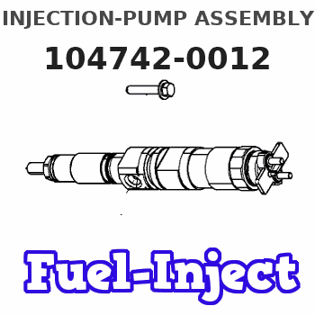
Information injection-pump assembly
ZEXEL
104742-0012
1047420012
MAZDA
SLG113800B
slg113800b
Rating:
Cross reference number
ZEXEL
104742-0012
1047420012
MAZDA
SLG113800B
slg113800b
Zexel num
Bosch num
Firm num
Name
Calibration Data:
Adjustment conditions
Test oil
1404 Test oil ISO4113orSAEJ967d
1404 Test oil ISO4113orSAEJ967d
Test oil temperature
degC
45
45
50
Nozzle
105780-0060
Bosch type code
NP-DN0SD1510
Nozzle holder
105780-2150
Opening pressure
MPa
13
13
13.3
Opening pressure
kgf/cm2
133
133
136
Injection pipe
157805-7320
Injection pipe
Inside diameter - outside diameter - length (mm) mm 2-6-450
Inside diameter - outside diameter - length (mm) mm 2-6-450
Joint assembly
157641-4720
Tube assembly
157641-4020
Transfer pump pressure
kPa
20
20
20
Transfer pump pressure
kgf/cm2
0.2
0.2
0.2
Direction of rotation (viewed from drive side)
Right R
Right R
Injection timing adjustment
Pump speed
r/min
1000
1000
1000
Average injection quantity
mm3/st.
65.1
64.6
65.6
Difference in delivery
mm3/st.
4
Basic
*
Injection timing adjustment_02
Pump speed
r/min
1950
1950
1950
Average injection quantity
mm3/st.
24.7
16.2
33.2
Injection timing adjustment_03
Pump speed
r/min
1875
1875
1875
Average injection quantity
mm3/st.
57.5
54
61
Injection timing adjustment_04
Pump speed
r/min
1600
1600
1600
Average injection quantity
mm3/st.
76
72.5
79.5
Injection timing adjustment_05
Pump speed
r/min
1000
1000
1000
Average injection quantity
mm3/st.
65.1
64.1
66.1
Injection timing adjustment_06
Pump speed
r/min
625
625
625
Average injection quantity
mm3/st.
52.6
50.1
55.1
Injection timing adjustment_07
Pump speed
r/min
400
400
400
Average injection quantity
mm3/st.
75.5
70
81
Injection quantity adjustment
Pump speed
r/min
1875
1875
1875
Average injection quantity
mm3/st.
57.5
54.5
60.5
Difference in delivery
mm3/st.
7
Basic
*
Injection quantity adjustment_02
Pump speed
r/min
2200
2200
2200
Average injection quantity
mm3/st.
8
Governor adjustment
Pump speed
r/min
365
365
365
Average injection quantity
mm3/st.
10.7
9.7
11.7
Difference in delivery
mm3/st.
2.5
Basic
*
Governor adjustment_02
Pump speed
r/min
500
500
500
Average injection quantity
mm3/st.
3
Governor adjustment_03
Pump speed
r/min
365
365
365
Average injection quantity
mm3/st.
10.7
9.7
11.7
Timer adjustment
Pump speed
r/min
100
100
100
Average injection quantity
mm3/st.
75
75
Basic
*
Speed control lever angle
Pump speed
r/min
365
365
365
Average injection quantity
mm3/st.
0
0
0
Remarks
Magnet OFF
Magnet OFF
0000000901
Pump speed
r/min
1500
1500
1500
Overflow quantity with S/T ON
cm3/min
624
474
774
Overflow quantity with S/T OFF
cm3/min
660
450
870
Remarks
OFF
OFF
Stop lever angle
Pump speed
r/min
1500
1500
1500
Pressure with S/T OFF
kPa
519.5
500
539
Pressure with S/T OFF
kgf/cm2
5.3
5.1
5.5
Basic
*
Stop lever angle_02
Pump speed
r/min
1500
1500
1500
Pressure with S/T OFF
kPa
519.5
500
539
Pressure with S/T OFF
kgf/cm2
5.3
5.1
5.5
Stop lever angle_03
Pump speed
r/min
1700
1700
1700
Pressure with S/T OFF
kPa
588.5
559
618
Pressure with S/T OFF
kgf/cm2
6
5.7
6.3
0000001101
Pump speed
r/min
1500
1500
1500
Timer stroke with S/T OFF
mm
2.4
2.2
2.6
Basic
*
_02
Pump speed
r/min
550
550
550
Timer stroke with S/T ON
mm
0.5
0.5
_03
Pump speed
r/min
1250
1250
1250
Timer stroke with S/T OFF
mm
0.5
_04
Pump speed
r/min
1500
1500
1500
Timer stroke with S/T OFF
mm
2.4
2.1
2.7
_05
Pump speed
r/min
1600
1600
1600
Timer stroke with S/T OFF
mm
3
2.5
3.5
_06
Pump speed
r/min
1700
1700
1700
Timer stroke with S/T OFF
mm
3.3
2.9
3.7
0000001201
Max. applied voltage
V
16
16
16
Test voltage
V
25
24
26
Timing setting
K dimension
mm
3.1
3
3.2
KF dimension
mm
5.5
5.4
5.6
MS dimension
mm
0.9
0.8
1
Pre-stroke
mm
0.45
0.43
0.47
Control lever angle alpha
deg.
40
36
44
Control lever angle beta
deg.
35
32
38
Test data Ex:
0000001801 CONTROL LEVER ANGLE
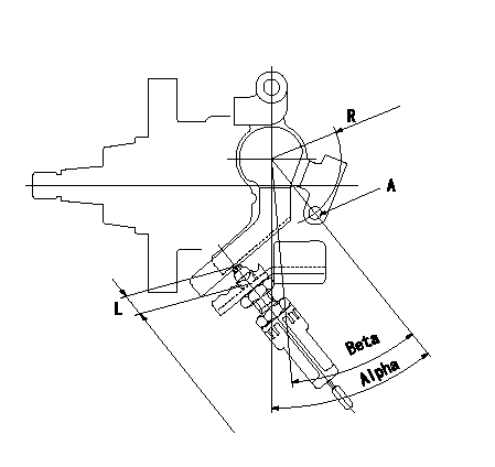
Control lever angle measurement position
Measure dimension L from end face of lever to flange.
A = lever angle measuring hole
----------
L=7.7~14.7mm
----------
L=7.7~14.7mm R=36mm Alpha=36~44deg Beta=32~38deg
----------
L=7.7~14.7mm
----------
L=7.7~14.7mm R=36mm Alpha=36~44deg Beta=32~38deg
0000001901 POTENTIOMETER ADJUSTMENT
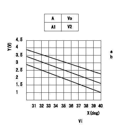
Adjustment of the potentiometer
Adjust the potentiometer to output voltage V1 at the full speed position.
With the control lever turned from the idle position to the full speed position, connect the connector wiring so that voltage increases
With the control lever in the idle position, confirm that the output voltage is within the range shown in the graph. Record the output voltage.
Vi = applied voltage
A = lever angle (deg)
Vo = output voltage (V)
Y = output voltage a (V)
X = Beta angle (deg)
----------
Vi=10.00V V1=8.4+-0.03V a=8.4-Beta/60*10 b=0.3+Beta/60*0.5
----------
Vi=10V A1=0deg Idle V2=(a+-b)V a=8.4-Beta/60*10 b=0.3+Beta/60*0.5
----------
Vi=10.00V V1=8.4+-0.03V a=8.4-Beta/60*10 b=0.3+Beta/60*0.5
----------
Vi=10V A1=0deg Idle V2=(a+-b)V a=8.4-Beta/60*10 b=0.3+Beta/60*0.5
0000002001 V-FICD ADJUSTMENT
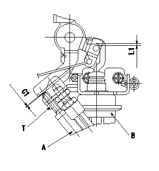
Temperature adjustment stopper adjustment
At the idle position, adjust so that the clearance between the control lever and the temperature adjustment stopper C1.
Adjustment of the V-FICD
Move the bracket in the direction of the arrow to adjust the clearance between the V-actuator rod and the control lever pin to L1.
A:Temperature adjustment stopper
B:V-actuator
----------
L1=2+0.5mm C1=0.3+-0.1mm
----------
C1=0.3+-0.1mm L1=2+0.5mm T=10~13N-m(1~1.3kgf-m)
----------
L1=2+0.5mm C1=0.3+-0.1mm
----------
C1=0.3+-0.1mm L1=2+0.5mm T=10~13N-m(1~1.3kgf-m)
Information:
Adjustto conform and correspond to specifications.Checkto observe for satisfactory conditions, accuracy, safety or performance.Exchangeto trade a worn or failing component for a remanufactured or rebuilt component.Inspectto examine closely, in critical appraisal, while testing or evaluating components or systems.Inspect/Rebuild or Exchangeto examine closely, then making the decision on repair option (i.e. Rebuild or Exchange).Lubricateto apply a lubricant (oil, grease, etc.) as specified for reducing friction, heat and wear between solid surfaces.Protective Devicesindicators such as gauges, lights, emergency shutoffs, etc., that alert an operator that a potential problem may exist. Failure to respond to these indicators in a timely manner could result in serious engine damage.Rebuildto repair a worn or failing component with new parts, components and/or remanufactured components.Replaceto install something new, remanufactured or rebuilt in place of an existing worn or failing component.Service Hours (Electrical)records the time (clock hours) the engine is actually running but does not reflect variations in speed, load, etc. Some engines are equipped with mechanical service meters reading in Service Meter Units (SMU). The Maintenance Schedules are developed for clock hours or fuel consumption. For most users, clock hours are the standard interval for maintenance and SMU's can be roughly equal to clock hours. However, Caterpillar recommends that fuel consumption be used as the preferred method of determining intervals rather than SMU's or clock hours.Interval Categories
Engine components can generally be grouped into speed sensitive and load sensitive categories. The maintenance interval for each item listed in the Maintenance Schedule is based on either engine speed or load. Speed sensitive items such as water pumps and air compressors are not primarily affected by the operating load on your engine. The load on an engine will not significantly accelerate the repair or replacement cycle for speed sensitive items.The maintenance intervals established for speed sensitive items are based on service hours. Load sensitive items such as piston rings and cylinder liners are affected by the operating load on your engine. Generally speaking, the lower the load, the longer the engine life. Conversely, the higher the load, the shorter the engine life. A heavy load on an engine will accelerate the repair or replacement cycle for load sensitive items.Load sensitive items are normally internal engine components. The amount of fuel consumed is directly related to the load on your engine.The maintenance interval for load sensitive items includes fuel consumption, since the amount of fuel consumed is directly related to the load on your engine.Caterpillar recommends performing maintenance on load sensitive items at maintenance intervals based on the quantity of fuel consumed.
Engine components can generally be grouped into speed sensitive and load sensitive categories. The maintenance interval for each item listed in the Maintenance Schedule is based on either engine speed or load. Speed sensitive items such as water pumps and air compressors are not primarily affected by the operating load on your engine. The load on an engine will not significantly accelerate the repair or replacement cycle for speed sensitive items.The maintenance intervals established for speed sensitive items are based on service hours. Load sensitive items such as piston rings and cylinder liners are affected by the operating load on your engine. Generally speaking, the lower the load, the longer the engine life. Conversely, the higher the load, the shorter the engine life. A heavy load on an engine will accelerate the repair or replacement cycle for load sensitive items.Load sensitive items are normally internal engine components. The amount of fuel consumed is directly related to the load on your engine.The maintenance interval for load sensitive items includes fuel consumption, since the amount of fuel consumed is directly related to the load on your engine.Caterpillar recommends performing maintenance on load sensitive items at maintenance intervals based on the quantity of fuel consumed.