Information injection-pump assembly
ZEXEL
104742-0011
1047420011
MAZDA
SLG113800A
slg113800a
Rating:
Cross reference number
ZEXEL
104742-0011
1047420011
MAZDA
SLG113800A
slg113800a
Zexel num
Bosch num
Firm num
Name
Calibration Data:
Adjustment conditions
Test oil
1404 Test oil ISO4113orSAEJ967d
1404 Test oil ISO4113orSAEJ967d
Test oil temperature
degC
45
45
50
Nozzle
105780-0060
Bosch type code
NP-DN0SD1510
Nozzle holder
105780-2150
Opening pressure
MPa
13
13
13.3
Opening pressure
kgf/cm2
133
133
136
Injection pipe
157805-7320
Injection pipe
Inside diameter - outside diameter - length (mm) mm 2-6-450
Inside diameter - outside diameter - length (mm) mm 2-6-450
Joint assembly
157641-4720
Tube assembly
157641-4020
Transfer pump pressure
kPa
20
20
20
Transfer pump pressure
kgf/cm2
0.2
0.2
0.2
Direction of rotation (viewed from drive side)
Right R
Right R
Injection timing adjustment
Pump speed
r/min
1000
1000
1000
Average injection quantity
mm3/st.
65.1
64.6
65.6
Difference in delivery
mm3/st.
4
Basic
*
Oil temperature
degC
50
48
52
Remarks
OFF
OFF
Injection timing adjustment_02
Pump speed
r/min
400
390
410
Average injection quantity
mm3/st.
78.6
78.6
78.6
Oil temperature
degC
48
46
50
Injection timing adjustment_03
Pump speed
r/min
625
615
635
Average injection quantity
mm3/st.
54.2
54.2
54.2
Oil temperature
degC
50
48
52
Injection timing adjustment_04
Pump speed
r/min
1000
990
1010
Average injection quantity
mm3/st.
65.1
64.1
66.1
Difference in delivery
mm3/st.
4.5
Oil temperature
degC
50
48
52
Injection timing adjustment_05
Pump speed
r/min
1600
1590
1610
Average injection quantity
mm3/st.
75.6
75.6
75.6
Oil temperature
degC
50
48
52
Injection quantity adjustment
Pump speed
r/min
1875
1875
1875
Average injection quantity
mm3/st.
57.5
54.5
60.5
Difference in delivery
mm3/st.
7
Basic
*
Oil temperature
degC
50
48
52
Remarks
OFF
OFF
Injection quantity adjustment_02
Pump speed
r/min
2200
2200
2200
Average injection quantity
mm3/st.
8
Oil temperature
degC
52
50
54
Remarks
OFF
OFF
Injection quantity adjustment_03
Pump speed
r/min
1875
1865
1885
Average injection quantity
mm3/st.
57.5
54
61
Difference in delivery
mm3/st.
7.5
Oil temperature
degC
50
48
52
Injection quantity adjustment_04
Pump speed
r/min
1950
1940
1960
Average injection quantity
mm3/st.
25.5
25.5
25.5
Oil temperature
degC
50
48
52
Governor adjustment
Pump speed
r/min
365
365
365
Average injection quantity
mm3/st.
12.3
11.3
13.3
Difference in delivery
mm3/st.
2.5
Basic
*
Oil temperature
degC
48
46
50
Remarks
OFF
OFF
Governor adjustment_02
Pump speed
r/min
365
355
375
Average injection quantity
mm3/st.
12.3
10.8
13.8
Difference in delivery
mm3/st.
3
Oil temperature
degC
48
46
50
Timer adjustment
Pump speed
r/min
100
100
100
Average injection quantity
mm3/st.
75
75
Basic
*
Oil temperature
degC
48
46
50
Timer adjustment_02
Pump speed
r/min
100
90
110
Average injection quantity
mm3/st.
75
75
Oil temperature
degC
48
46
50
Speed control lever angle
Pump speed
r/min
325
325
325
Average injection quantity
mm3/st.
0
0
0
Oil temperature
degC
48
46
50
Remarks
Magnet OFF at idling position
Magnet OFF at idling position
0000000901
Pump speed
r/min
1500
1500
1500
Oil temperature
degC
50
48
52
Remarks
MEASURE
MEASURE
Stop lever angle
Pump speed
r/min
1500
1500
1500
Pressure with S/T OFF
kPa
520
500
540
Pressure with S/T OFF
kgf/cm2
5.3
5.1
5.5
Basic
*
Oil temperature
degC
50
48
52
Stop lever angle_02
Pump speed
r/min
1500
1490
1510
Pressure with S/T OFF
kPa
520
500
540
Pressure with S/T OFF
kgf/cm2
5.3
5.1
5.5
Oil temperature
degC
50
48
52
0000001101
Pump speed
r/min
1500
1500
1500
Timer stroke with S/T OFF
mm
2.4
2.2
2.6
Basic
*
Oil temperature
degC
50
48
52
_02
Pump speed
r/min
1500
1490
1510
Timer stroke with S/T OFF
mm
2.4
2
2.8
Oil temperature
degC
50
48
52
_03
Pump speed
r/min
1600
1590
1610
Timer stroke with S/T OFF
mm
3.1
2.6
3.6
Oil temperature
degC
50
48
52
_04
Pump speed
r/min
1700
1690
1710
Timer stroke with S/T OFF
mm
3.3
2.8
3.9
Oil temperature
degC
50
48
52
0000001201
Max. applied voltage
V
16
16
16
Test voltage
V
25
24
26
Timing setting
K dimension
mm
3.1
3
3.2
KF dimension
mm
5.5
5.4
5.6
MS dimension
mm
0.9
0.8
1
Pre-stroke
mm
0.45
0.43
0.47
Control lever angle alpha
deg.
40
36
44
Control lever angle beta
deg.
35
32
38
Test data Ex:
0000001801 POTENTIOMETER ADJUSTMENT
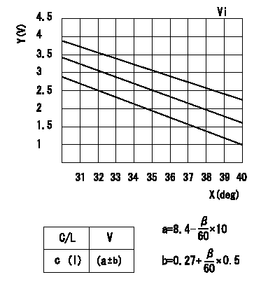
Potentiometer adjustment
Adjust the potentiometer so that the output voltage is V1 at the full speed position.
With the control lever turned from the idle position to the full speed position, connect the connector wiring so that voltage increases
With the control lever in the idle position, confirm that the output voltage is within the range shown in the graph. Record the output voltage.
Vi:Applied voltage
Y:Output voltage a
X:Angle beta
C/L: lever position
I:Idle
V:Output voltage
----------
Vi=10V V1=8.4+-0.03V
----------
Vi=10V c=0deg
----------
Vi=10V V1=8.4+-0.03V
----------
Vi=10V c=0deg
0000001901 V-FICD ADJUSTMENT
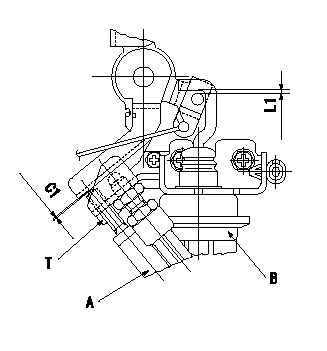
Temperature adjustment stopper adjustment
At the idle position, adjust so that the clearance between the control lever and the temperature adjustment stopper C1.
Adjustment of the V-FICD
Move the bracket in the direction of the arrow to adjust the clearance between the V-actuator rod and the control lever pin to L1.
A:Temperature adjustment stopper
B:V-actuator
----------
C1=0.3+-0.1mm L1=2+0.5mm
----------
C1=0.3+-0.1mm L1=2+0.5mm T=9.8~12.7N-m(1~1.3kgf-m)
----------
C1=0.3+-0.1mm L1=2+0.5mm
----------
C1=0.3+-0.1mm L1=2+0.5mm T=9.8~12.7N-m(1~1.3kgf-m)
Information:
Coolant is essential to control engine operating temperatures and make components last longer. Poorly maintained coolant can actually shorten component life by causing a chain reaction of heat problems. Excessive heat can cause: * Hot spots that crack steel, notably in cylinder heads* Bubble pockets that form on cylinder surfaces and result in liner pitting* Oil to degrade, leading to component damage* Lacquer and shellac build up on precision hydraulic parts* Oil additives to break down and transmission clutches to slipS O S Coolant Analysis is the best way to monitor the condition of your coolant and your cooling system. The two level program, based on samples you submit, shows the condition of coolant and the cooling system.Level I: Basic Coolant Maintenance Check
Checks for correct chemical balance for proper heat and corrosion control. Tests for: * glycol* SCA concentrations* pH* conductivityS O S Coolant Analysis reports results and makes recommendations, usually within 24 hours.The concentration of SCA should be checked regularly for overconcentration or underconcentration. This should be done with test kits, or S O S Coolant Analysis (Level I) at the Every 250 Service Hours interval.Further coolant analysis is recommended at twice a year or after every 1000 service hours.For example, suppose considerable deposits are found in the water jacket areas on the external cooling system, yet coolant additive concentrations were carefully maintained. Chances are that the coolant water had minerals which deposited on the engine over time.One way to verify the water condition, or to be sure of new water at fill time, is to have a coolant analysis conducted. Full water analysis can sometimes be obtained locally by contacting your local water utility company or an agricultural agent. Private laboratories are also available.Caterpillar recommends S O S Level II Coolant Analysis.Level II: Comprehensive Cooling System Analysis
Completely analyzes coolant and coolant effects on the cooling system. Level II Analysis provides: * full Level I analysis* visual properties inspection* metal corrosion and contaminant identification* identification of built up impurities that point to corrosion and scaling problems BEFORE they lead to costly repairs.Level II Analysis provides a simple, clear report of results, and makes recommendations for the lowest cost corrective options.For more information of coolant analysis and how it can help manage your equipment, see your Caterpillar dealer. Consult your Caterpillar dealer for complete information and assistance in establishing an S O S analysis program for your engine(s).