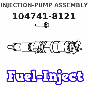
Information injection-pump assembly
ZEXEL
104741-8121
1047418121
MITSUBISHI
ME444303
me444303
Rating:
Compare Prices: .
As an associate, we earn commssions on qualifying purchases through the links below

High Pressure Diesel Pump 321-4936 ME444303 104741-8122, Compatible For 306 307B/C/D 308C/D 4M40 Engines, Direct Fit Excavator Fuel System Assembly
Sdvbfjnm 【Compatible Models】: Compatible For excavator models 306, 307B/C/D, 308C/D 4M40 diesel engines, ensuring precise high-pressure fuel delivery and system compatibility. || 【Direct Replacement】: Engineered to match original specifications seamless installation and stable fuel pressure performance. || 【Durable Design】: Constructed reinforced alloy materials to withstand extreme pressure and harsh construction site environments. || 【OME Compliance】: Rigorously tested to meet OME 321-4936 ME444303 104741-8122 standards durability and fuel efficiency. || 【Universal Application】: Supports reliable fuel supply excavators in both construction and industrial operations.
Sdvbfjnm 【Compatible Models】: Compatible For excavator models 306, 307B/C/D, 308C/D 4M40 diesel engines, ensuring precise high-pressure fuel delivery and system compatibility. || 【Direct Replacement】: Engineered to match original specifications seamless installation and stable fuel pressure performance. || 【Durable Design】: Constructed reinforced alloy materials to withstand extreme pressure and harsh construction site environments. || 【OME Compliance】: Rigorously tested to meet OME 321-4936 ME444303 104741-8122 standards durability and fuel efficiency. || 【Universal Application】: Supports reliable fuel supply excavators in both construction and industrial operations.

Compatible With 306 307B C D 308C D Fuel Pump 4M40 High Pressure Diesel Pump 321-4936 ME444303 104741-8122 Excavator Parts
QEDFGH Dependable Diesel Injection Pump || This diesel injection pump is designed to deliver consistent fuel flow, supporting stable engine operation. It is compatible with a variety of diesel engines and suited Compatible With regular use. || Quality Craftsmanship || Made from robust materials, this diesel fuel pump is built to handle regular wear and tear, providing reliable functionality Compatible With your vehicle or equipment. || Steady Fuel Delivery || This pump ensures even fuel distribution, helping to maintain consistent engine operation and smoother functionality. || Simple Installation and Wide Fitment || Designed Compatible With easy setup, this diesel injection pump Compatible With a range of models and makes, making it a practical choice Compatible With repairs or replacements. || Supports Engine PerCompatible Withmance || By maintaining stable fuel pressure and flow, this pump aids in reliable engine operation and starting, even in varying conditions.
QEDFGH Dependable Diesel Injection Pump || This diesel injection pump is designed to deliver consistent fuel flow, supporting stable engine operation. It is compatible with a variety of diesel engines and suited Compatible With regular use. || Quality Craftsmanship || Made from robust materials, this diesel fuel pump is built to handle regular wear and tear, providing reliable functionality Compatible With your vehicle or equipment. || Steady Fuel Delivery || This pump ensures even fuel distribution, helping to maintain consistent engine operation and smoother functionality. || Simple Installation and Wide Fitment || Designed Compatible With easy setup, this diesel injection pump Compatible With a range of models and makes, making it a practical choice Compatible With repairs or replacements. || Supports Engine PerCompatible Withmance || By maintaining stable fuel pressure and flow, this pump aids in reliable engine operation and starting, even in varying conditions.

Compatible With 306 307B C D 308C D Fuel Pump 4M40 High Pressure Diesel Pump 321-4936 ME444303 104741-8122 Excavator Parts
IUVPTAF The performance of high-pressure fuel pumps is strong, reflected in efficient atomization, rapid response, and precise fuel supply || Stable pressure, one-way valve and buffer at the oil outlet to prevent fuel backflow and reduce oil pressure pulse || Equipped with safety valves and pressure limiters to achieve multiple protections. Can work stably in complex environments || Integrated design, energy-saving and environmentally friendly, reduces fuel consumption, and the fuel pump also achieves intelligent control || Compatible With 306 307B C D 308C D Fuel Pump 4M40 High Pressure Diesel Pump 321-4936 ME444303 104741-8122 Excavator Parts
IUVPTAF The performance of high-pressure fuel pumps is strong, reflected in efficient atomization, rapid response, and precise fuel supply || Stable pressure, one-way valve and buffer at the oil outlet to prevent fuel backflow and reduce oil pressure pulse || Equipped with safety valves and pressure limiters to achieve multiple protections. Can work stably in complex environments || Integrated design, energy-saving and environmentally friendly, reduces fuel consumption, and the fuel pump also achieves intelligent control || Compatible With 306 307B C D 308C D Fuel Pump 4M40 High Pressure Diesel Pump 321-4936 ME444303 104741-8122 Excavator Parts
You can express buy:
USD 2021.98
14-06-2025
14-06-2025
Original Parts 307D 4M40 Fuel · Pumps for excavator Diesel Pump ME444303 104741-8122
USD 416.9
14-06-2025
14-06-2025
Diesel Fuel Injection Pump 104641-8121 VE4/11F1000RNP2618 ME444303
Cross reference number
ZEXEL
104741-8121
1047418121
MITSUBISHI
ME444303
me444303
Zexel num
Bosch num
Firm num
Name
Calibration Data:
Adjustment conditions
Test oil
1404 Test oil ISO4113orSAEJ967d
1404 Test oil ISO4113orSAEJ967d
Test oil temperature
degC
45
45
50
Nozzle
105780-0060
Bosch type code
NP-DN0SD1510
Nozzle holder
105780-2150
Opening pressure
MPa
13
13
13.3
Opening pressure
kgf/cm2
133
133
136
Injection pipe
157805-7320
Injection pipe
Inside diameter - outside diameter - length (mm) mm 2-6-450
Inside diameter - outside diameter - length (mm) mm 2-6-450
Joint assembly
157641-4720
Tube assembly
157641-4020
Transfer pump pressure
kPa
20
20
20
Transfer pump pressure
kgf/cm2
0.2
0.2
0.2
Direction of rotation (viewed from drive side)
Right R
Right R
Injection timing adjustment
Pump speed
r/min
900
900
900
Average injection quantity
mm3/st.
63.8
63.3
64.3
Difference in delivery
mm3/st.
5
Basic
*
Oil temperature
degC
50
48
52
Injection timing adjustment_02
Pump speed
r/min
600
600
600
Average injection quantity
mm3/st.
63.2
59.2
67.2
Oil temperature
degC
50
48
52
Injection timing adjustment_03
Pump speed
r/min
750
750
750
Average injection quantity
mm3/st.
62.6
58.6
66.6
Oil temperature
degC
50
48
52
Injection timing adjustment_04
Pump speed
r/min
900
900
900
Average injection quantity
mm3/st.
63.8
62.8
64.8
Difference in delivery
mm3/st.
5.5
Basic
*
Oil temperature
degC
50
48
52
Injection timing adjustment_05
Pump speed
r/min
1000
1000
1000
Average injection quantity
mm3/st.
64.6
62.1
67.1
Oil temperature
degC
50
48
52
Injection quantity adjustment
Pump speed
r/min
1125
1125
1125
Average injection quantity
mm3/st.
23.9
21.4
26.4
Difference in delivery
mm3/st.
7.5
Basic
*
Oil temperature
degC
50
48
52
Injection quantity adjustment_02
Pump speed
r/min
1125
1125
1125
Average injection quantity
mm3/st.
23.9
20.9
26.9
Difference in delivery
mm3/st.
8
Basic
*
Oil temperature
degC
50
48
52
Injection quantity adjustment_03
Pump speed
r/min
1250
1250
1250
Average injection quantity
mm3/st.
5
Oil temperature
degC
50
48
52
Governor adjustment
Pump speed
r/min
540
540
540
Average injection quantity
mm3/st.
19.6
17.6
21.6
Difference in delivery
mm3/st.
2
Basic
*
Oil temperature
degC
50
48
52
Governor adjustment_02
Pump speed
r/min
540
540
540
Average injection quantity
mm3/st.
19.6
17.1
22.1
Difference in delivery
mm3/st.
2.5
Basic
*
Oil temperature
degC
50
48
52
Timer adjustment
Pump speed
r/min
100
100
100
Average injection quantity
mm3/st.
95
75
145
Basic
*
Oil temperature
degC
48
46
50
Remarks
Full
Full
Timer adjustment_02
Pump speed
r/min
100
100
100
Average injection quantity
mm3/st.
95
75
145
Oil temperature
degC
48
46
50
Remarks
Full
Full
Speed control lever angle
Pump speed
r/min
540
540
540
Average injection quantity
mm3/st.
0
0
0
Oil temperature
degC
50
48
52
Remarks
Magnet OFF at idling position
Magnet OFF at idling position
0000000901
Pump speed
r/min
900
900
900
Overflow quantity
cm3/min
710
580
840
Oil temperature
degC
50
48
52
Stop lever angle
Pump speed
r/min
900
900
900
Pressure
kPa
559
539
579
Pressure
kgf/cm2
5.7
5.5
5.9
Basic
*
Oil temperature
degC
50
48
52
Stop lever angle_02
Pump speed
r/min
800
800
800
Pressure
kPa
520
471
569
Pressure
kgf/cm2
5.3
4.8
5.8
Oil temperature
degC
50
48
52
Stop lever angle_03
Pump speed
r/min
900
900
900
Pressure
kPa
559
530
588
Pressure
kgf/cm2
5.7
5.4
6
Basic
*
Oil temperature
degC
50
48
52
Stop lever angle_04
Pump speed
r/min
1000
1000
1000
Pressure
kPa
598
549
647
Pressure
kgf/cm2
6.1
5.6
6.6
Oil temperature
degC
50
48
52
0000001101
Pump speed
r/min
900
900
900
Timer stroke
mm
1.5
1.3
1.7
Basic
*
Oil temperature
degC
50
48
52
_02
Pump speed
r/min
900
900
900
Timer stroke
mm
1.5
1.1
1.9
Basic
*
Oil temperature
degC
50
48
52
_03
Pump speed
r/min
1000
1000
1000
Timer stroke
mm
2.5
1.9
3.1
Oil temperature
degC
50
48
52
_04
Pump speed
r/min
1100
1100
1100
Timer stroke
mm
2.9
2.4
3.3
Oil temperature
degC
50
48
52
0000001201
Max. applied voltage
V
16
16
16
Test voltage
V
25
24
26
Timing setting
K dimension
mm
3.3
3.2
3.4
KF dimension
mm
5.8
5.7
5.9
MS dimension
mm
2
1.9
2.1
Control lever angle alpha
deg.
57
53
61
Control lever angle beta
deg.
25
20
30
Test data Ex:
0000001801 W-CSD ADJUSTMENT
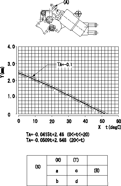
Adjustment of the W-CSD
Adjust the timer stroke
1. Adjust the timer stroke B so that it is as described in the graph. (graph TA)
2) Adjust using screw (A) to obtain the timer stroke determined in step 1.
X:Temperature t (deg C)
Y:Timer stroke TA (mm)
(S) Cold advance
(R) Cooling water temperature (deg C)
(T) Timer piston stroke (mm)
(B) Standard point
----------
----------
a=20degC b=0degC c=1.63+-4mm d=2.46+-0.6mm
----------
----------
a=20degC b=0degC c=1.63+-4mm d=2.46+-0.6mm
0000001901 TAMPER PROOF
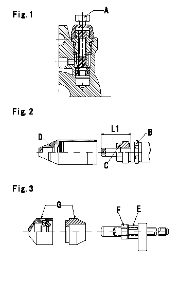
Tamperproof installation procedure
A:Position of break
B:Rubber vibration damper
C:Nut
D:Cap
E:Nut
F:Nut
G:Cap
L1:Inspection dimension
Fig. 1 Regulating valve seal
1) Target breaking torque T1
2) Maximum allowable breaking torque T2
3) Because the cap and the regulating valve are fixed using the MEC process, the bolt cannot be loosened after the bolt has been broken.
Fig.2 Full load adjusting screw
1) Confirm the position of the rubber vibration damper (B) and then tighten nut (C) to the torque T3.
Fig. 3 Maximum speed adjusting screw
1) Tighten nut (E) to the torque T4.
2) To prevent nut (E) from turning together, fix (E) using the tool, then tighten nut (F) to torque T4.
----------
L1=23~28mm T1=5~6.9N-m(0.5~0.69kgf-m) T2=9N-m(0.9kgf-m) T3=7~9N-m(0.7~0.9kgf-m) T4=6~9N-m(0.6~0.9kgf-m)
----------
L1=23~28mm
----------
L1=23~28mm T1=5~6.9N-m(0.5~0.69kgf-m) T2=9N-m(0.9kgf-m) T3=7~9N-m(0.7~0.9kgf-m) T4=6~9N-m(0.6~0.9kgf-m)
----------
L1=23~28mm
Information:
TECHNICAL INFORMATION BULLETIN JAN. 15th, 2003
EXCAVATORS
WHEEL LOADERS
ENGINES 322C: (EMR, MAR);
325C: (CRB, CSJ, JLC, JLD, DTF)
950G II: (AYL, AYB);
962G II: (AYE, BAB)
3126B: (BMA)
Component Code(s) 1408SUBJECT: A NEW INJECTION ACTUATION PRESSURE CONTROL VALVE CONNECTOR INCREASES ENGINE OPERATION
PROBLEM:
The injection actuation pressure (IAP) control valve connector may have been assembled incorrectly on some 3126B engine harnesses. This can lead to intermittent engine operation or can cause the engine to stop.
SOLUTION:
If your machine exhibits symptoms of intermittent engine operation or abruptly stopping, the IAP control valve connector should be disconnected from the machine, examined for solenoid contact problems and re-installed using a correct procedure.
Procedure for installing the IAP control valve connector
This procedure will describe how to properly install the 232-4367 Harness.
Required Parts
Qty Part Number Description
1 232-4367 Harness
Procure the part that is listed in the table.
Illustration 1. Left Side of a 3126B Engine on a D6N.
(1) IAP Control Valve
(2) IAP Control Valve Connector
Note: Illustration 1 is from a D6N that is equipped with a 3126B for photographical purposes. The location of the IAP Control Valve is the same for your machine.
Disconnect the IAP control valve connector (2) from the IAP Control Valve (1). See Illustration 1.
Cut the two wires directly behind the connector.
Using wire strippers, strip the ends of the two wires.
Install the 232-4367 Harness, by crimping the stripped wires inside the splice.
Note: Take care to connect the pink wire to the pink wire on one hand and the purple wire to the purple wire on the other hand.
Heat both heat shrinkable tubes in order to insulate both the splices.
Reconnect the repaired harness to the IAP Control Valve (1).
COPYRIGHT 2003 CATERPILLAR
ALL RIGHTS RESERVED