Information injection-pump assembly
BOSCH
9 460 614 472
9460614472
ZEXEL
104741-7140
1047417140
KOMATSU
6205711170
6205711170

Rating:
Cross reference number
BOSCH
9 460 614 472
9460614472
ZEXEL
104741-7140
1047417140
KOMATSU
6205711170
6205711170
Zexel num
Bosch num
Firm num
Name
104741-7140
9 460 614 472
6205711170 KOMATSU
INJECTION-PUMP ASSEMBLY
S4D95L K
S4D95L K
Calibration Data:
Adjustment conditions
Test oil
1404 Test oil ISO4113orSAEJ967d
1404 Test oil ISO4113orSAEJ967d
Test oil temperature
degC
45
45
50
Nozzle
105780-0060
Bosch type code
NP-DN0SD1510
Nozzle holder
105780-2150
Opening pressure
MPa
13
13
13.3
Opening pressure
kgf/cm2
133
133
136
Injection pipe
157805-7320
Injection pipe
Inside diameter - outside diameter - length (mm) mm 2-6-450
Inside diameter - outside diameter - length (mm) mm 2-6-450
Joint assembly
157641-4720
Tube assembly
157641-4020
Transfer pump pressure
kPa
20
20
20
Transfer pump pressure
kgf/cm2
0.2
0.2
0.2
Direction of rotation (viewed from drive side)
Right R
Right R
Injection timing adjustment
Pump speed
r/min
400
400
400
Average injection quantity
mm3/st.
55
54.5
55.5
Difference in delivery
mm3/st.
4
Basic
*
Oil temperature
degC
48
46
50
Injection timing adjustment_02
Pump speed
r/min
400
400
400
Average injection quantity
mm3/st.
55
54
56
Difference in delivery
mm3/st.
4
Basic
*
Oil temperature
degC
48
46
50
Injection timing adjustment_03
Pump speed
r/min
800
800
800
Average injection quantity
mm3/st.
78.7
74.7
82.7
Oil temperature
degC
50
48
52
Injection timing adjustment_04
Pump speed
r/min
1300
1300
1300
Average injection quantity
mm3/st.
78.2
74.2
82.2
Oil temperature
degC
50
48
52
Injection quantity adjustment
Pump speed
r/min
1425
1425
1425
Average injection quantity
mm3/st.
28.5
24.5
32.5
Difference in delivery
mm3/st.
7
Basic
*
Oil temperature
degC
50
48
52
Injection quantity adjustment_02
Pump speed
r/min
1600
1600
1600
Average injection quantity
mm3/st.
3
Oil temperature
degC
50
48
52
Injection quantity adjustment_03
Pump speed
r/min
1425
1425
1425
Average injection quantity
mm3/st.
28.5
24
33
Difference in delivery
mm3/st.
7
Basic
*
Oil temperature
degC
50
48
52
Governor adjustment
Pump speed
r/min
400
400
400
Average injection quantity
mm3/st.
9.6
7.6
11.6
Difference in delivery
mm3/st.
2
Basic
*
Oil temperature
degC
48
46
50
Governor adjustment_02
Pump speed
r/min
400
400
400
Average injection quantity
mm3/st.
9.6
7.1
12.1
Difference in delivery
mm3/st.
2
Basic
*
Oil temperature
degC
48
46
50
Timer adjustment
Pump speed
r/min
100
100
100
Average injection quantity
mm3/st.
86.5
81.5
91.5
Basic
*
Oil temperature
degC
48
46
50
Remarks
Full
Full
Timer adjustment_02
Pump speed
r/min
100
100
100
Average injection quantity
mm3/st.
86.5
81.5
91.5
Oil temperature
degC
48
46
50
Remarks
Full
Full
Speed control lever angle
Pump speed
r/min
400
400
400
Average injection quantity
mm3/st.
0
0
0
Oil temperature
degC
48
46
50
Remarks
Magnet OFF at idling position
Magnet OFF at idling position
0000000901
Pump speed
r/min
1300
1300
1300
Overflow quantity
cm3/min
380
250
510
Oil temperature
degC
50
48
52
Stop lever angle
Pump speed
r/min
1300
1300
1300
Pressure
kPa
471
451
491
Pressure
kgf/cm2
4.8
4.6
5
Basic
*
Oil temperature
degC
50
48
52
Stop lever angle_02
Pump speed
r/min
1300
1300
1300
Pressure
kPa
471
442
500
Pressure
kgf/cm2
4.8
4.5
5.1
Basic
*
Oil temperature
degC
50
48
52
0000001101
Pump speed
r/min
1300
1300
1300
Timer stroke
mm
1.6
1.4
1.8
Basic
*
Oil temperature
degC
50
48
52
_02
Pump speed
r/min
1100
1100
1100
Timer stroke
mm
0.5
0
1
Oil temperature
degC
50
48
52
_03
Pump speed
r/min
1300
1300
1300
Timer stroke
mm
1.6
1.3
1.9
Basic
*
Oil temperature
degC
50
48
52
_04
Pump speed
r/min
1425
1425
1425
Timer stroke
mm
3.3
2.6
3.8
Oil temperature
degC
50
48
52
0000001201
Max. applied voltage
V
8
8
8
Test voltage
V
13
12
14
Timing setting
K dimension
mm
2.8
2.7
2.9
KF dimension
mm
5
4.9
5.1
MS dimension
mm
1.7
1.6
1.8
Pre-stroke
mm
0.45
0.43
0.47
Control lever angle alpha
deg.
16
12
20
Control lever angle beta
deg.
32
27
37
Test data Ex:
0000001801 STARTING I/Q ADJUSTMENT

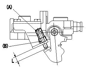
Starting Q decrease lever adjustment
At injection quantity adjustment, adjust using the bolt so that the starting injection quantity is as specified. Fix using the nut. (Tightening torque T)
Bolt (A) protrusion: L
(B) = nut
----------
L=7.4~11.1mm T=6~9N-m(0.6~0.9kgf-m)
----------
L=7.4~11.1mm
----------
L=7.4~11.1mm T=6~9N-m(0.6~0.9kgf-m)
----------
L=7.4~11.1mm
Information:
The following installation procedures are to be used in conjunction with Special Instruction, SEHS9173, "Installation of Automatic Ether Injection System (AEIS)". This instruction outlines the extra steps needed to install components of the MPPS system along with routing and clipping of harnesses.
Before starting the installation procedure, make certain that the machine disconnect switch is in the off position.Do not perform any procedure, outlined in this publication, or order any parts until you read and understand the information contained within.Reference: Service Manual, SENR4705-02 and Special Instruction, SEHS9173.Necessary Parts
The following parts list shows some part numbers in the deleted column. This means that these parts are called out on the Automatic Ether Injection System (AEIS) retrofit instructions but should not be ordered, since they are replaced by different parts for Multipoint Pressure Sensing (MPPS). This only applies if an AEIS retrofit is also being performed. Installation of 3E3778 Ether Control Group
* The 3E3778 Control Group is required for the MPPS system.If MPPS is being installed in conjunction with an AEIS retrofit, substitute the 3E3778 Control Group for the 9X5303 Control Group called out in the Automatic Ether Injection System Special Instruction, SEHS9173. Substitute a 3E3779 Film for the 9X4542 Film.If MPPS is being added to an existing AEIS system, check the electronic control box installed with the AEIS system to see if it is a 3E3778 or a 9X5303 Control Group. If a 9X5303 Control Group is installed, replace it with a 3E3778 Control Group and 3E3779 Film. Follow the control box installation instructions outlined in the AEIS installation Special Instruction. Be sure to install the 8R7105 Wire As. between the control and mounting plate to ground the control box to the frame. If an MPPS identification film is needed for a language other than English, refer to the following chart for the part number of the film for a specific language. Installation of 3E3530 Electronic Control Group [(PWM) Oil Pressure Sensor]
1. Remove the 6T4949 Oil Pressure Switch and the O-ring port adapter from the turbo oil adapter on the right rear of the engine (switch on the bottom port with 405-GY attached to it)2. Install a 3E5276 Adapter (1) in the port using a 3J7354 Seal (2) and a 6V4589 O-ring Seal (3).3. Install 3E3530 Electronic Control Group (4) [PWM Oil Pressure Sensor] onto 3E5276 Adapter (1).4. Using a 5P7854 Clip (5), loosely install the 3E3530 Control Group on the flywheel housing as shown using a 1T0720 Bolt (6) and 5P1075 Washer (7).Installation of Wiring Harnesses
Installation of 8E7966 Ether (Engine) Wiring Harness
* The 9N4537 Engine Harness on the AEIS is replaced with 8E7966 Harness Assembly.If MPPS is being installed at the same time as AEIS, substitute 8E7966 Harness Assembly for 9N4537 Harness Assembly called out in the AEIS installation Special Instructions.If MPPS is being added to an existing AEIS, disconnect the old 9N4537 Harness Assembly from the 9X0377 Control Group (water temperature sensor), 6T4361 Speed Sensor and the ether chassis harness.Install the 8E7966 Harness Assembly following the same installation
Have questions with 104741-7140?
Group cross 104741-7140 ZEXEL
Komatsu
Komatsu
104741-7140
9 460 614 472
6205711170
INJECTION-PUMP ASSEMBLY
S4D95L
S4D95L