Information injection-pump assembly
ZEXEL
104741-6820
1047416820
ISUZU
8970126510
8970126510
Rating:
Cross reference number
ZEXEL
104741-6820
1047416820
ISUZU
8970126510
8970126510
Zexel num
Bosch num
Firm num
Name
Calibration Data:
Adjustment conditions
Test oil
1404 Test oil ISO4113orSAEJ967d
1404 Test oil ISO4113orSAEJ967d
Test oil temperature
degC
45
45
50
Nozzle
105780-0060
Bosch type code
NP-DN0SD1510
Nozzle holder
105780-2150
Opening pressure
MPa
13
13
13.3
Opening pressure
kgf/cm2
133
133
136
Injection pipe
157805-7320
Injection pipe
Inside diameter - outside diameter - length (mm) mm 2-6-450
Inside diameter - outside diameter - length (mm) mm 2-6-450
Joint assembly
157641-4720
Tube assembly
157641-4020
Transfer pump pressure
kPa
20
20
20
Transfer pump pressure
kgf/cm2
0.2
0.2
0.2
Direction of rotation (viewed from drive side)
Right R
Right R
Injection timing adjustment
Pump speed
r/min
800
800
800
Average injection quantity
mm3/st.
40
39.5
40.5
Difference in delivery
mm3/st.
3.5
Basic
*
Oil temperature
degC
50
48
52
Injection timing adjustment_02
Pump speed
r/min
400
400
400
Average injection quantity
mm3/st.
39.7
39.7
39.7
Oil temperature
degC
48
46
50
Injection timing adjustment_03
Pump speed
r/min
500
500
500
Average injection quantity
mm3/st.
38.1
38.1
38.1
Oil temperature
degC
48
46
50
Injection timing adjustment_04
Pump speed
r/min
800
800
800
Average injection quantity
mm3/st.
40
39
41
Difference in delivery
mm3/st.
3.5
Basic
*
Oil temperature
degC
50
48
52
Injection timing adjustment_05
Pump speed
r/min
1175
1175
1175
Average injection quantity
mm3/st.
42.9
42.9
42.9
Oil temperature
degC
50
48
52
Injection quantity adjustment
Pump speed
r/min
1250
1250
1250
Average injection quantity
mm3/st.
20
17
23
Difference in delivery
mm3/st.
4
Basic
*
Oil temperature
degC
50
48
52
Injection quantity adjustment_02
Pump speed
r/min
1350
1350
1350
Average injection quantity
mm3/st.
3
Oil temperature
degC
50
48
52
Injection quantity adjustment_03
Pump speed
r/min
1250
1250
1250
Average injection quantity
mm3/st.
20
17
23
Difference in delivery
mm3/st.
4
Oil temperature
degC
50
48
52
Governor adjustment
Pump speed
r/min
350
350
350
Average injection quantity
mm3/st.
19.9
17.9
21.9
Difference in delivery
mm3/st.
2
Basic
*
Oil temperature
degC
48
46
50
Governor adjustment_02
Pump speed
r/min
350
350
350
Average injection quantity
mm3/st.
19.9
17.9
21.9
Difference in delivery
mm3/st.
2
Oil temperature
degC
48
46
50
Timer adjustment
Pump speed
r/min
100
100
100
Average injection quantity
mm3/st.
50
47
53
Basic
*
Oil temperature
degC
48
46
50
Remarks
Full
Full
Timer adjustment_02
Pump speed
r/min
100
100
100
Average injection quantity
mm3/st.
50
47
53
Oil temperature
degC
48
46
50
Speed control lever angle
Pump speed
r/min
350
350
350
Average injection quantity
mm3/st.
0
0
0
Oil temperature
degC
48
46
50
Remarks
Magnet OFF at idling position
Magnet OFF at idling position
0000000901
Pump speed
r/min
800
800
800
Overflow quantity
cm3/min
290
160
420
Oil temperature
degC
50
48
52
Stop lever angle
Pump speed
r/min
800
800
800
Pressure
kPa
235
215
255
Pressure
kgf/cm2
2.4
2.2
2.6
Basic
*
Oil temperature
degC
50
48
52
Stop lever angle_02
Pump speed
r/min
800
800
800
Pressure
kPa
235
215
255
Pressure
kgf/cm2
2.4
2.2
2.6
Basic
*
Oil temperature
degC
50
48
52
0000001101
Pump speed
r/min
800
800
800
Timer stroke
mm
1.1
0.9
1.3
Basic
*
Oil temperature
degC
50
48
52
_02
Pump speed
r/min
650
650
650
Timer stroke
mm
0.5
0.1
1.3
Oil temperature
degC
50
48
52
_03
Pump speed
r/min
800
800
800
Timer stroke
mm
1.1
0.9
1.3
Basic
*
Oil temperature
degC
50
48
52
_04
Pump speed
r/min
1175
1175
1175
Timer stroke
mm
2.4
2.1
2.8
Oil temperature
degC
50
48
52
0000001201
Max. applied voltage
V
8
8
8
Test voltage
V
13
12
14
Timing setting
K dimension
mm
2.8
2.7
2.9
KF dimension
mm
5
4.9
5.1
MS dimension
mm
1.8
1.7
1.9
Pre-stroke
mm
0.45
0.43
0.47
Control lever angle alpha
deg.
25
21
29
Control lever angle beta
deg.
23
18
28
Test data Ex:
0000001801 STARTING I/Q ADJUSTMENT
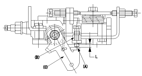
Starting injection quantity adjustment
Adjust the adjusting bolt A so that the starting injection quantity adjustment is within the standards. Fix using the nut B.
(C) Stop lever
L:Adjustment dimensions
----------
L=2~8.5mm
----------
L=2~8.5mm
----------
L=2~8.5mm
----------
L=2~8.5mm
Information:
The information supplied in this service letter may not be valid after the termination date of this program. Do not perform the work outlined in this Service Letter after the termination date without first contacting your Caterpillar product analyst.
Termination Date
March 31, 1997Problem
Improvements have been made to the remanufactured unit injectors that are used in various 3114 and 3116 Engines. All of the former 0R3002, 0R3003, 0R3190, 0R3389, 0R3580, 0R3742, 0R4368, 0R4369, 0R4370, 0R4374, and 0R4376 Remanufactured Unit Injectors need to be removed from Parts Stock.
Action Required
Remove all 0R3002, 0R3003, 0R3190, 0R3389, 0R3580, 0R3742, 0R4368, 0R4369, 0R4370, 0R4374, and 0R4376 Remanufactured Unit Injectors from Parts Stock.
When ordering parts, refer to the attached chart until the information is available in a permanent publication.
Service Claim Allowances
Submit one claim for all 0R3002, 0R3003, 0R3190, 0R3389, 0R3580, 0R3742, 0R4368, 0R4369, 0R4370, 0R4374, and 0R4376 Remanufactured Unit Injectors removed from Parts Stock.
TEPS Dealers should refer to their warranty bullitin for proper claiming and disposition.
Parts Disposition
All injectors removed from Parts Stock are to be returned as cores for remanufacturing.
U.S. and Canadian Dealers
Return all 0R3002, 0R3003, 0R3190, 0R3389, 0R3580, 0R3742, 0R4368, 0R4369, 0R4370, 0R4374, and 0R4376 Remanufactured Unit Injectors that are removed from Parts Stock and a copy of the claim to:
Caterpillar Inc.
Attn: Bill Harland - Warranty Review
501 Cardinal Drive
Corinth, MS 38834
All Other Dealers
Handle the parts in accordance with your Warranty Bulletin on Remanufactured Engines and Components, refer to the topic "Disposition of the Core Under Warranty".
Attach.(1-UNIT INJECTOR CHART)3114 & 3116 Unit Injector Chart