Information injection-pump assembly
ZEXEL
104741-6791
1047416791
ISUZU
8970134691
8970134691

Rating:
Cross reference number
ZEXEL
104741-6791
1047416791
ISUZU
8970134691
8970134691
Zexel num
Bosch num
Firm num
Name
Calibration Data:
Adjustment conditions
Test oil
1404 Test oil ISO4113orSAEJ967d
1404 Test oil ISO4113orSAEJ967d
Test oil temperature
degC
45
45
50
Nozzle
105000-2010
Bosch type code
NP-DN12SD12TT
Nozzle holder
105780-2080
Opening pressure
MPa
14.7
14.7
15.19
Opening pressure
kgf/cm2
150
150
155
Injection pipe
Inside diameter - outside diameter - length (mm) mm 2-6-840
Inside diameter - outside diameter - length (mm) mm 2-6-840
Transfer pump pressure
kPa
20
20
20
Transfer pump pressure
kgf/cm2
0.2
0.2
0.2
Direction of rotation (viewed from drive side)
Right R
Right R
Injection timing adjustment
Pump speed
r/min
1000
1000
1000
Average injection quantity
mm3/st.
41.7
41.2
42.2
Difference in delivery
mm3/st.
3.5
Basic
*
Oil temperature
degC
50
48
52
Injection timing adjustment_02
Pump speed
r/min
500
500
500
Average injection quantity
mm3/st.
38.3
38.3
38.3
Oil temperature
degC
48
46
50
Injection timing adjustment_03
Pump speed
r/min
700
700
700
Average injection quantity
mm3/st.
34.4
34.4
34.4
Oil temperature
degC
50
48
52
Injection timing adjustment_04
Pump speed
r/min
1000
1000
1000
Average injection quantity
mm3/st.
41.7
40.7
42.7
Difference in delivery
mm3/st.
3.5
Basic
*
Oil temperature
degC
50
48
52
Injection timing adjustment_05
Pump speed
r/min
1450
1450
1450
Average injection quantity
mm3/st.
43.9
40.9
46.9
Oil temperature
degC
50
48
52
Injection timing adjustment_06
Pump speed
r/min
1800
1800
1800
Average injection quantity
mm3/st.
47.5
44
51
Difference in delivery
mm3/st.
5.5
Oil temperature
degC
50
48
52
Injection timing adjustment_07
Pump speed
r/min
2100
2100
2100
Average injection quantity
mm3/st.
10.6
7.6
13.6
Difference in delivery
mm3/st.
4
Oil temperature
degC
52
50
54
Injection timing adjustment_08
Pump speed
r/min
1800
1800
1800
Average injection quantity
mm3/st.
47.5
44.5
50.5
Difference in delivery
mm3/st.
5.5
Oil temperature
degC
50
48
52
Injection quantity adjustment
Pump speed
r/min
2100
2100
2100
Average injection quantity
mm3/st.
10.6
7.6
13.6
Difference in delivery
mm3/st.
4
Basic
*
Oil temperature
degC
52
50
54
Injection quantity adjustment_02
Pump speed
r/min
2300
2300
2300
Average injection quantity
mm3/st.
5
Oil temperature
degC
52
50
54
Governor adjustment
Pump speed
r/min
425
425
425
Average injection quantity
mm3/st.
5.5
3.5
7.5
Difference in delivery
mm3/st.
2
Basic
*
Oil temperature
degC
48
46
50
Governor adjustment_02
Pump speed
r/min
425
425
425
Average injection quantity
mm3/st.
5.5
3.5
7.5
Oil temperature
degC
48
46
50
Timer adjustment
Pump speed
r/min
100
100
100
Average injection quantity
mm3/st.
60
60
100
Basic
*
Oil temperature
degC
48
46
50
Remarks
Full
Full
Timer adjustment_02
Pump speed
r/min
100
100
100
Average injection quantity
mm3/st.
80
60
100
Oil temperature
degC
48
46
50
Speed control lever angle
Pump speed
r/min
390
390
390
Average injection quantity
mm3/st.
0
0
0
Oil temperature
degC
48
46
50
Remarks
Magnet OFF at idling position
Magnet OFF at idling position
0000000901
Pump speed
r/min
1600
1600
1600
Overflow quantity with S/T ON
cm3/min
490
360
620
Overflow quantity with S/T OFF
cm3/min
580
450
710
Oil temperature
degC
50
48
52
Stop lever angle
Pump speed
r/min
1600
1600
1600
Pressure with S/T OFF
kPa
450
430
489
Pressure with S/T OFF
kgf/cm2
4.6
4.4
5
Basic
*
Oil temperature
degC
50
48
52
Stop lever angle_02
Pump speed
r/min
1600
1600
1600
Pressure with S/T OFF
kPa
450
430
489
Pressure with S/T OFF
kgf/cm2
4.6
4.4
5
Basic
*
Oil temperature
degC
50
48
52
0000001101
Pump speed
r/min
1600
1600
1600
Timer stroke with S/T OFF
mm
2.2
2
2.4
Basic
*
Oil temperature
degC
50
48
52
_02
Pump speed
r/min
900
900
900
Timer stroke with S/T ON
mm
0.5
0.5
Oil temperature
degC
50
48
52
_03
Pump speed
r/min
1500
1500
1500
Timer stroke with S/T OFF
mm
0.5
Oil temperature
degC
50
48
52
_04
Pump speed
r/min
1600
1600
1600
Timer stroke with S/T OFF
mm
2.2
2
2.4
Basic
*
Oil temperature
degC
50
48
52
_05
Pump speed
r/min
1800
1800
1800
Timer stroke with S/T OFF
mm
7
6.7
7.4
Oil temperature
degC
50
48
52
0000001201
Max. applied voltage
V
8
8
8
Test voltage
V
13
12
14
Timing setting
K dimension
mm
2.8
2.7
2.9
KF dimension
mm
5
4.9
5.1
MS dimension
mm
1
0.9
1.1
Pre-stroke
mm
0.45
0.43
0.47
Control lever angle alpha
deg.
18
14
22
Control lever angle beta
deg.
31
26
36
Test data Ex:
0000001801 V-FICD ADJUSTMENT

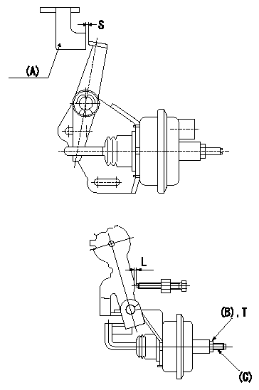
Adjustment of the V-FICD
1. Adjust to obtain S.
2. Confirm that L1 is obtained when negative pressure P1 (P2 ) is applied to the actuator.
To adjust the stroke adjust the actuator's stroke adjusting screw (C).
(A) Control lever
(B) Lock nut (Tightening torque T)
(C) Stroke adjusting screw
----------
S=2+1mm L=0.7+-0.2mm P1=-46.7kPa P2=-350mmHg
----------
S=2+1mm L=0.7+-0.2mm T=1.2~1.5N-m{0.12~0.15kgf-m}
----------
S=2+1mm L=0.7+-0.2mm P1=-46.7kPa P2=-350mmHg
----------
S=2+1mm L=0.7+-0.2mm T=1.2~1.5N-m{0.12~0.15kgf-m}
0000001901 A/T PLATE ADJUSTMENT

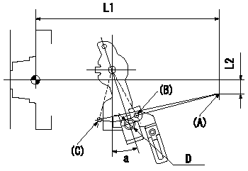
A/T plate adjustment
Rotate the control lever from the idle position (B) to the full-speed position (C).
Adjust the A/T plate (A) so that (A) (C) - (A) (B) = L3, and fix.
(B): B idle position
(C): B' full
----------
L3=32.9+-1mm
----------
L1=169.8mm L2=12.4mm a=18+-4deg D=Dia.9.2mm
----------
L3=32.9+-1mm
----------
L1=169.8mm L2=12.4mm a=18+-4deg D=Dia.9.2mm
0000002001 POTENTIOMETER ADJUSTMENT

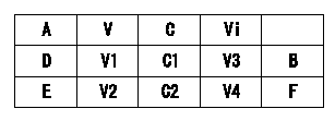
A = lever position
B = adjusting point
Vi = applied voltage
V = output voltage
C = lever angle
D = full speed
E = idle
F = confirmation point
----------
----------
V1=8.2+-0.03V V2=3.94--V C1=31+-5deg C2=0deg V3=10V V4=10V
----------
----------
V1=8.2+-0.03V V2=3.94--V C1=31+-5deg C2=0deg V3=10V V4=10V
Information:
Termination Date
October 31, 1993Problem
Certain 2S7264 and 3S1467 Fuel Injection Pump Assemblies need to be removed from parts stock.
Action Required
Remove all 2S7264 and 3S1467 Fuel Injection Pump Assemblies from parts stock with date codes of December 1992 through March 1993. The date code appears at the bottom of the part number label on the pump box. The first two numbers indicate the month and the next two numbers indicate the year as shown in the example below:
Service Claim Allowances
Submit one claim for all 2S7264 and 3S1467 Fuel Injection Pump Assemblies removed from parts stock.
US and Canadian Dealers Only - When submitting a parts stock claim use 99Z00007 in the Product Identification Number Field.
Parts Disposition
U.S. And Canadian Dealers
Return all 2S7264 and 3S1467 Fuel Injection Pump Assemblies that are removed from parts stock and a copy of the claim to:
Caterpillar Inc.
Memory Lane
B Receiving
York, PA 17402
Attention: Quality Dept./PI7318
All Other Dealers
Handle the parts in accordance with your Warranty Bulletin on warranty parts handling.