Information injection-pump assembly
ZEXEL
104741-6720
1047416720
ISUZU
8970189430
8970189430

Rating:
Cross reference number
ZEXEL
104741-6720
1047416720
ISUZU
8970189430
8970189430
Zexel num
Bosch num
Firm num
Name
Calibration Data:
Adjustment conditions
Test oil
1404 Test oil ISO4113orSAEJ967d
1404 Test oil ISO4113orSAEJ967d
Test oil temperature
degC
45
45
50
Nozzle
105780-0060
Bosch type code
NP-DN0SD1510
Nozzle holder
105780-2150
Opening pressure
MPa
13
13
13.3
Opening pressure
kgf/cm2
133
133
136
Injection pipe
157805-7320
Injection pipe
Inside diameter - outside diameter - length (mm) mm 2-6-450
Inside diameter - outside diameter - length (mm) mm 2-6-450
Joint assembly
157641-4720
Tube assembly
157641-4020
Transfer pump pressure
kPa
20
20
20
Transfer pump pressure
kgf/cm2
0.2
0.2
0.2
Direction of rotation (viewed from drive side)
Right R
Right R
(Solenoid timer adjustment condition)
OFF
Timer measuring device installation position
Low pressure side LOW PRESSURE SIDE
Low pressure side LOW PRESSURE SIDE
Injection timing adjustment
Pump speed
r/min
750
750
750
Boost pressure
kPa
42.7
41.4
44
Boost pressure
mmHg
320
310
330
Average injection quantity
mm3/st.
50.5
50
51
Difference in delivery
mm3/st.
4.5
Basic
*
Oil temperature
degC
50
48
52
Remarks
CBS
CBS
Injection timing adjustment_02
Pump speed
r/min
1100
1100
1100
Boost pressure
kPa
72
70.7
73.3
Boost pressure
mmHg
540
530
550
Average injection quantity
mm3/st.
67.7
67.2
68.2
Difference in delivery
mm3/st.
5.5
Basic
*
Oil temperature
degC
50
48
52
Remarks
Full
Full
Injection timing adjustment_03
Pump speed
r/min
400
400
400
Boost pressure
kPa
0
0
0
Boost pressure
mmHg
0
0
0
Average injection quantity
mm3/st.
38.1
38.1
38.1
Oil temperature
degC
48
46
50
Injection timing adjustment_04
Pump speed
r/min
600
600
600
Boost pressure
kPa
18.7
17.4
20
Boost pressure
mmHg
140
130
150
Average injection quantity
mm3/st.
38.6
38.6
38.6
Oil temperature
degC
50
48
52
Injection timing adjustment_05
Pump speed
r/min
750
750
750
Boost pressure
kPa
42.7
41.4
44
Boost pressure
mmHg
320
310
330
Average injection quantity
mm3/st.
50.5
49.5
51.5
Difference in delivery
mm3/st.
4.5
Basic
*
Oil temperature
degC
50
48
52
Injection timing adjustment_06
Pump speed
r/min
1100
1100
1100
Boost pressure
kPa
72
70.7
73.3
Boost pressure
mmHg
540
530
550
Average injection quantity
mm3/st.
67.7
66.7
68.7
Difference in delivery
mm3/st.
5.5
Basic
*
Oil temperature
degC
50
48
52
Injection timing adjustment_07
Pump speed
r/min
1100
1100
1100
Boost pressure
kPa
0
0
0
Boost pressure
mmHg
0
0
0
Average injection quantity
mm3/st.
53.1
53.1
53.1
Oil temperature
degC
50
48
52
Injection timing adjustment_08
Pump speed
r/min
1900
1900
1900
Boost pressure
kPa
72
70.7
73.3
Boost pressure
mmHg
540
530
550
Average injection quantity
mm3/st.
71.2
71.2
71.2
Oil temperature
degC
50
48
52
Injection quantity adjustment
Pump speed
r/min
2300
2300
2300
Boost pressure
kPa
72
70.7
73.3
Boost pressure
mmHg
540
530
550
Average injection quantity
mm3/st.
23.4
20.4
26.4
Difference in delivery
mm3/st.
7
Basic
*
Oil temperature
degC
52
50
54
Injection quantity adjustment_02
Pump speed
r/min
2400
2400
2400
Boost pressure
kPa
72
70.7
73.3
Boost pressure
mmHg
540
530
550
Average injection quantity
mm3/st.
12
Oil temperature
degC
52
50
54
Injection quantity adjustment_03
Pump speed
r/min
2300
2300
2300
Boost pressure
kPa
72
70.7
73.3
Boost pressure
mmHg
540
530
550
Average injection quantity
mm3/st.
23.4
20.4
26.4
Difference in delivery
mm3/st.
7
Oil temperature
degC
52
50
54
Governor adjustment
Pump speed
r/min
425
425
425
Boost pressure
kPa
0
0
0
Boost pressure
mmHg
0
0
0
Average injection quantity
mm3/st.
5.6
3.6
7.6
Difference in delivery
mm3/st.
2
Basic
*
Oil temperature
degC
48
46
50
Governor adjustment_02
Pump speed
r/min
425
425
425
Boost pressure
kPa
0
0
0
Boost pressure
mmHg
0
0
0
Average injection quantity
mm3/st.
5.6
3.6
7.6
Difference in delivery
mm3/st.
2
Oil temperature
degC
48
46
50
Timer adjustment
Pump speed
r/min
100
100
100
Boost pressure
kPa
0
0
0
Boost pressure
mmHg
0
0
0
Average injection quantity
mm3/st.
85
80
90
Basic
*
Oil temperature
degC
48
46
50
Remarks
IDLE
IDLE
Timer adjustment_02
Pump speed
r/min
100
100
100
Boost pressure
kPa
0
0
0
Boost pressure
mmHg
0
0
0
Average injection quantity
mm3/st.
85
80
90
Oil temperature
degC
48
46
50
Speed control lever angle
Pump speed
r/min
425
425
425
Boost pressure
kPa
0
0
0
Boost pressure
mmHg
0
0
0
Average injection quantity
mm3/st.
0
0
0
Oil temperature
degC
48
46
50
Remarks
Magnet OFF at idling position
Magnet OFF at idling position
0000000901
Pump speed
r/min
1500
1500
1500
Boost pressure
kPa
72
70.7
73.3
Boost pressure
mmHg
540
530
550
Overflow quantity with S/T ON
cm3/min
560
430
690
Overflow quantity with S/T OFF
cm3/min
640
510
770
Oil temperature
degC
50
48
52
Stop lever angle
Pump speed
r/min
1500
1500
1500
Boost pressure
kPa
72
70.7
73.3
Boost pressure
mmHg
540
530
550
Pressure with S/T OFF
kPa
490
470
510
Pressure with S/T OFF
kgf/cm2
5
4.8
5.2
Basic
*
Oil temperature
degC
50
48
52
Stop lever angle_02
Pump speed
r/min
1250
1250
1250
Boost pressure
kPa
72
70.7
73.3
Boost pressure
mmHg
540
530
550
Pressure with S/T OFF
kPa
412
373
451
Pressure with S/T OFF
kgf/cm2
4.2
3.8
4.6
Oil temperature
degC
50
48
52
Stop lever angle_03
Pump speed
r/min
1500
1500
1500
Boost pressure
kPa
72
70.7
73.3
Boost pressure
mmHg
540
530
550
Pressure with S/T OFF
kPa
490
461
519
Pressure with S/T OFF
kgf/cm2
5
4.7
5.3
Basic
*
Oil temperature
degC
50
48
52
Stop lever angle_04
Pump speed
r/min
1700
1700
1700
Boost pressure
kPa
72
70.7
73.3
Boost pressure
mmHg
540
530
550
Pressure with S/T OFF
kPa
559
520
598
Pressure with S/T OFF
kgf/cm2
5.7
5.3
6.1
Oil temperature
degC
50
48
52
Stop lever angle_05
Pump speed
r/min
1900
1900
1900
Boost pressure
kPa
72
70.7
73.3
Boost pressure
mmHg
540
530
550
Pressure with S/T OFF
kPa
618
579
657
Pressure with S/T OFF
kgf/cm2
6.3
5.9
6.7
Oil temperature
degC
50
48
52
0000001101
Pump speed
r/min
1500
1500
1500
Boost pressure
kPa
72
70.7
73.3
Boost pressure
mmHg
540
530
550
Timer stroke with S/T OFF
mm
4.5
4.3
4.7
Basic
*
Oil temperature
degC
50
48
52
_02
Pump speed
r/min
425
425
425
Boost pressure
kPa
72
70.7
73.3
Boost pressure
mmHg
540
530
550
Timer stroke with S/T ON
mm
1.2
Oil temperature
degC
48
46
50
_03
Pump speed
r/min
750
750
750
Boost pressure
kPa
72
70.7
73.3
Boost pressure
mmHg
540
530
550
Timer stroke with S/T ON
mm
1
1
Oil temperature
degC
50
48
52
_04
Pump speed
r/min
1250
1250
1250
Boost pressure
kPa
72
70.7
73.3
Boost pressure
mmHg
540
530
550
Timer stroke with S/T OFF
mm
1.3
0.9
1.7
Oil temperature
degC
50
48
52
_05
Pump speed
r/min
1500
1500
1500
Boost pressure
kPa
72
70.7
73.3
Boost pressure
mmHg
540
530
550
Timer stroke with S/T OFF
mm
4.5
4.3
4.7
Basic
*
Oil temperature
degC
50
48
52
_06
Pump speed
r/min
1900
1900
1900
Boost pressure
kPa
72
70.7
73.3
Boost pressure
mmHg
540
530
550
Timer stroke with S/T OFF
mm
7.4
7.1
7.8
Oil temperature
degC
50
48
52
0000001201
Max. applied voltage
V
8
8
8
Test voltage
V
13
12
14
Timing setting
K dimension
mm
3.1
3
3.2
KF dimension
mm
5.5
5.4
5.6
MS dimension
mm
1
0.9
1.1
BCS stroke
mm
2.7
2.5
2.9
Pre-stroke
mm
0.45
0.43
0.47
Control lever angle alpha
deg.
24
20
28
Control lever angle beta
deg.
48
43
53
Test data Ex:
0000001801 POTENTIOMETER ADJUSTMENT
Adjust the potentiometer so that the output voltage is V1 at the idle lever position (applied voltage Vi).
----------
V1=1.3+-0.03V Vi=10V
----------
----------
V1=1.3+-0.03V Vi=10V
----------
0000001901 V-FICD ADJUSTMENT

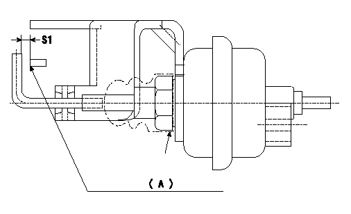
Adjustment of the V-FICD
1. Adjust the actuator rod to obtain S1.
2. Apply negative pressure P1 to the actuator and confirm the full stroke.
(A) Control lever (Idling position)
----------
S1=1+1mm P1=-53.3kPa(-400mmHg)
----------
S1=1+1mm
----------
S1=1+1mm P1=-53.3kPa(-400mmHg)
----------
S1=1+1mm
0000002001 A/T PLATE ADJUSTMENT

A/T plate adjustment
Adjust the A/T plate (A) so that (A)(C) - (A)(B) = L3 when the control lever is moved from the idle position (B) to the full speed position (C), then fix.
(B) Idle position
(C) Full
----------
L3=32.9+-1mm
----------
L1=36mm L2=174mm
----------
L3=32.9+-1mm
----------
L1=36mm L2=174mm
0000002101 STARTING I/Q ADJUSTMENT

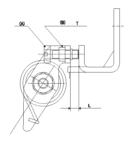
Starting injection quantity adjustment
Adjust adjusting bolt (A) so that the start injection quantity is within the specifications and fix using nut (B). (Torque T)
Make bolt protrusion L.
----------
L=3~6mm T=3.4~4.9N-m(0.35~0.5kgf-m)
----------
L=3~6mm T=3.4~4.9N-m(0.35~0.5kgf-m)
----------
L=3~6mm T=3.4~4.9N-m(0.35~0.5kgf-m)
----------
L=3~6mm T=3.4~4.9N-m(0.35~0.5kgf-m)
Information:
Caterpillar: Confidential Yellow
PSP FOR REPLACING ERODED CYLINDER HEAD INJECTOR SLEEVES IN CERTAIN IT14B INTEGRATED TOOLCARRIERS; E110B, E120B, E200B, EL2 00B, 213B, 214B, 224B, E240B, EL240B EXCAVATORS; 446 BACKHOE LOADERS; AND 3114 AND 3116 INDUSTRIAL AND GENERATOR SET EN GINES - PS0456 - US, CANADA, CACO, LTD COFA - REVISED 10/90
The information supplied in this service letter may not be valid after the termination date of this program. Do not perform the work outlined in this Service Letter after the termination date without first contacting your Caterpillar product analyst.
(Revised October 1990) U-130 A-88 AU-86.1 1100, 1290 PS0456 This Program can only be administered after a failure occurs. The decision whether to apply the Program is made by the dealer. When reporting the repair, use "PS0456" as Part Number, "7755" as Group Number, and "96" as Description Code. If this Program is administered on E200B or EL200B Excavators, it is recommended that the June 22, 1990 Service Letter - PS4442 be done at the same time. This Revised Service Letter replaces the June 25, 1990 Service Letter. Changes have been made to add Affected Product. Termination Date
June 30, 1991
Problem
The fuel injector sleeves in the cylinder head of certain IT14B Integrated Toolcarriers; E110B, E120B, E200B, EL200B, 213B, 214B, 224B, E240B, and EL240B Excavators; 446 Backhoe Loaders; CB-434, CP-563, and CS-563 Compactors; AP-1050 Asphalt Pavers; and 3114 and 3116 Industrial and Generator Set Engines are subject to pitting and erosion due to fuel cavitation between the injector and the sleeve. The sleeves may pit or crack through, allowing fuel to contaminate the coolant. Coolant contaminated with fuel may also damage the radiator and coolant hoses.
Affected Product
Model Identification Number IT14B 3NJ1-42 E110B 8MF1-151 E120B 6JF1-212 E200B* 6KF1-439 6KG1-249 EL200B* 7DF1-986 213B 1EJ1-233, 236-245, 247, 248 214B