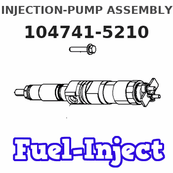
Information injection-pump assembly
BOSCH
9 460 614 443
9460614443
ZEXEL
104741-5210
1047415210
ISUZU
8970283230
8970283230
Rating:
Cross reference number
BOSCH
9 460 614 443
9460614443
ZEXEL
104741-5210
1047415210
ISUZU
8970283230
8970283230
Zexel num
Bosch num
Firm num
Name
104741-5210
9 460 614 443
8970283230 ISUZU
INJECTION-PUMP ASSEMBLY
4JB1CGT * K
4JB1CGT * K
Calibration Data:
Adjustment conditions
Test oil
1404 Test oil ISO4113orSAEJ967d
1404 Test oil ISO4113orSAEJ967d
Test oil temperature
degC
45
45
50
Nozzle
105000-2010
Bosch type code
NP-DN12SD12TT
Nozzle holder
105780-2080
Opening pressure
MPa
14.7
14.7
15.19
Opening pressure
kgf/cm2
150
150
155
Injection pipe
Inside diameter - outside diameter - length (mm) mm 2-6-840
Inside diameter - outside diameter - length (mm) mm 2-6-840
Transfer pump pressure
kPa
20
20
20
Transfer pump pressure
kgf/cm2
0.2
0.2
0.2
Direction of rotation (viewed from drive side)
Left L
Left L
Injection timing adjustment
Pump speed
r/min
1250
1250
1250
Boost pressure
kPa
46.7
45.4
48
Boost pressure
mmHg
350
340
360
Average injection quantity
mm3/st.
49.1
48.6
50.6
Difference in delivery
mm3/st.
4.5
Basic
*
Oil temperature
degC
50
48
52
Remarks
CBS
CBS
Injection timing adjustment_02
Pump speed
r/min
1250
1250
1250
Boost pressure
kPa
93.3
92
94.6
Boost pressure
mmHg
700
690
710
Average injection quantity
mm3/st.
60.9
60.4
61.4
Difference in delivery
mm3/st.
3.5
Basic
*
Oil temperature
degC
50
48
52
Remarks
Full
Full
Injection timing adjustment_03
Pump speed
r/min
600
600
600
Boost pressure
kPa
13.3
12
14.6
Boost pressure
mmHg
100
90
110
Average injection quantity
mm3/st.
35.8
31.8
39.8
Oil temperature
degC
48
46
50
Injection timing adjustment_04
Pump speed
r/min
750
750
750
Boost pressure
kPa
24
22.7
25.3
Boost pressure
mmHg
180
170
190
Average injection quantity
mm3/st.
38.2
38.2
38.2
Oil temperature
degC
50
48
52
Injection timing adjustment_05
Pump speed
r/min
900
900
900
Boost pressure
kPa
46.7
45.4
48
Boost pressure
mmHg
350
340
360
Average injection quantity
mm3/st.
48.2
48.2
48.2
Oil temperature
degC
50
48
52
Injection timing adjustment_06
Pump speed
r/min
1250
1250
1250
Boost pressure
kPa
46.7
45.4
48
Boost pressure
mmHg
350
340
360
Average injection quantity
mm3/st.
49.1
48.1
50.1
Difference in delivery
mm3/st.
4.5
Basic
*
Oil temperature
degC
50
48
52
Injection timing adjustment_07
Pump speed
r/min
1250
1250
1250
Boost pressure
kPa
93.3
92
94.6
Boost pressure
mmHg
700
690
710
Average injection quantity
mm3/st.
60.9
59.9
61.9
Difference in delivery
mm3/st.
3.5
Basic
*
Oil temperature
degC
50
48
52
Injection timing adjustment_08
Pump speed
r/min
1800
1800
1800
Boost pressure
kPa
93.3
92
94.6
Boost pressure
mmHg
700
690
710
Average injection quantity
mm3/st.
58.3
54.8
61.8
Difference in delivery
mm3/st.
5.5
Oil temperature
degC
50
48
52
Injection quantity adjustment
Pump speed
r/min
2300
2300
2300
Boost pressure
kPa
93.3
92
94.6
Boost pressure
mmHg
700
690
710
Average injection quantity
mm3/st.
16.5
13.5
19.5
Difference in delivery
mm3/st.
4.5
Basic
*
Oil temperature
degC
52
50
54
Injection quantity adjustment_02
Pump speed
r/min
2600
2600
2600
Boost pressure
kPa
93.3
92
94.6
Boost pressure
mmHg
700
690
710
Average injection quantity
mm3/st.
5
Oil temperature
degC
55
52
58
Injection quantity adjustment_03
Pump speed
r/min
2300
2300
2300
Boost pressure
kPa
93.3
92
94.6
Boost pressure
mmHg
700
690
710
Average injection quantity
mm3/st.
16.5
13.5
19.5
Difference in delivery
mm3/st.
4.5
Oil temperature
degC
52
50
54
Governor adjustment
Pump speed
r/min
375
375
375
Boost pressure
kPa
0
0
0
Boost pressure
mmHg
0
0
0
Average injection quantity
mm3/st.
7
5
9
Difference in delivery
mm3/st.
2
Basic
*
Oil temperature
degC
48
46
50
Governor adjustment_02
Pump speed
r/min
375
375
375
Boost pressure
kPa
0
0
0
Boost pressure
mmHg
0
0
0
Average injection quantity
mm3/st.
7
5
9
Difference in delivery
mm3/st.
2
Oil temperature
degC
48
46
50
Timer adjustment
Pump speed
r/min
100
100
100
Boost pressure
kPa
0
0
0
Boost pressure
mmHg
0
0
0
Average injection quantity
mm3/st.
80
60
100
Basic
*
Oil temperature
degC
48
46
50
Remarks
IDLE
IDLE
Timer adjustment_02
Pump speed
r/min
100
100
100
Boost pressure
kPa
0
0
0
Boost pressure
mmHg
0
0
0
Average injection quantity
mm3/st.
80
60
100
Oil temperature
degC
48
46
50
Speed control lever angle
Pump speed
r/min
375
375
375
Boost pressure
kPa
0
0
0
Boost pressure
mmHg
0
0
0
Average injection quantity
mm3/st.
0
0
0
Oil temperature
degC
48
46
50
Remarks
Magnet OFF at idling position
Magnet OFF at idling position
0000000901
Pump speed
r/min
1600
1600
1600
Boost pressure
kPa
93.3
92
94.6
Boost pressure
mmHg
700
690
710
Oil temperature
degC
50
48
52
Remarks
MEASURE
MEASURE
Stop lever angle
Pump speed
r/min
1600
1600
1600
Boost pressure
kPa
93.3
92
94.6
Boost pressure
mmHg
700
690
710
Pressure with S/T OFF
kPa
490
470
510
Pressure with S/T OFF
kgf/cm2
5
4.8
5.2
Basic
*
Oil temperature
degC
50
48
52
Stop lever angle_02
Pump speed
r/min
1050
1050
1050
Boost pressure
kPa
93.3
92
94.6
Boost pressure
mmHg
700
690
710
Pressure with S/T OFF
kPa
314
285
343
Pressure with S/T OFF
kgf/cm2
3.2
2.9
3.5
Oil temperature
degC
50
48
52
Stop lever angle_03
Pump speed
r/min
1600
1600
1600
Boost pressure
kPa
93.3
92
94.6
Boost pressure
mmHg
700
690
710
Pressure with S/T OFF
kPa
490
470
510
Pressure with S/T OFF
kgf/cm2
5
4.8
5.2
Basic
*
Oil temperature
degC
50
48
52
Stop lever angle_04
Pump speed
r/min
1800
1800
1800
Boost pressure
kPa
93.3
92
94.6
Boost pressure
mmHg
700
690
710
Pressure with S/T OFF
kPa
539
510
568
Pressure with S/T OFF
kgf/cm2
5.5
5.2
5.8
Oil temperature
degC
50
48
52
0000001101
Pump speed
r/min
1600
1600
1600
Boost pressure
kPa
93.3
92
94.6
Boost pressure
mmHg
700
690
710
Timer stroke with S/T OFF
mm
5
4.8
5.2
Basic
*
Oil temperature
degC
50
48
52
_02
Pump speed
r/min
520
520
520
Boost pressure
kPa
93.3
92
94.6
Boost pressure
mmHg
700
690
710
Timer stroke with S/T ON
mm
0.5
0.5
Oil temperature
degC
50
48
52
_03
Pump speed
r/min
1050
1050
1050
Boost pressure
kPa
93.3
92
94.6
Boost pressure
mmHg
700
690
710
Timer stroke with S/T OFF
mm
0.5
0.1
0.9
Oil temperature
degC
50
48
52
_04
Pump speed
r/min
1600
1600
1600
Boost pressure
kPa
93.3
92
94.6
Boost pressure
mmHg
700
690
710
Timer stroke with S/T OFF
mm
5
4.8
5.2
Basic
*
Oil temperature
degC
50
48
52
_05
Pump speed
r/min
1800
1800
1800
Boost pressure
kPa
93.3
92
94.6
Boost pressure
mmHg
700
690
710
Timer stroke with S/T OFF
mm
6.2
5.9
6.6
Oil temperature
degC
50
48
52
0000001201
Max. applied voltage
V
8
8
8
Test voltage
V
13
12
14
Timing setting
K dimension
mm
2.8
2.7
2.9
KF dimension
mm
5.5
5.4
5.6
MS dimension
mm
0.9
0.8
1
BCS stroke
mm
4.8
4.6
5
Pre-stroke
mm
0.45
0.43
0.47
Control lever angle alpha
deg.
18
14
22
Control lever angle beta
deg.
37
32
42
Test data Ex:
0000001801 V-FICD ADJUSTMENT
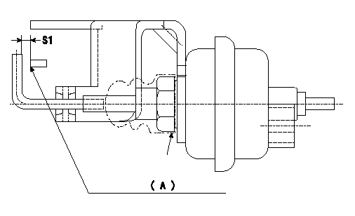
Adjustment of the V-FICD
1. Adjust the actuator rod to obtain S1.
2. Apply negative pressure P1 kPa {P2 mmHg} to the actuator and confirm that it moves through its full stroke.
(A) Control lever (Idling position)
----------
S1=1+1mm P1=-53.3kPa P2=-400mmHg
----------
S1=1+1mm
----------
S1=1+1mm P1=-53.3kPa P2=-400mmHg
----------
S1=1+1mm
Information:
Cut apart used filters to see contaminants. Use a 6V790S FilterCutter
to cut the filter housing.
Maintenance for Engines Using Heavy Fuel
Engines operating on heavy fuel must be carefully monitored and maintained.Service intervals must be strictly observed. Operators must be trained toperform a thorough service inspection.
"As Needed" Periodic Activities
Test fuel as it is delivered. Identify contaminant levels immediately and notify appropriate operations personnel.
Before storage, test for compatibility between fuel in the tanks and the fuel being purchased. Keep the fuel in separate tanks if possible.
Use regular S.O.S oil analysis to determine if there are wear particles in the oil, and maintain the proper TBN level.
Request infrared analysis on used oils to determine the effects of burning heavy fuel on the crankcase oil.
Daily Activities
Maintain and monitor fuel treatment equipment.
Record engine temperatures to assure adequate jacket water temperature, aftercooler temperature, and air intake temperature.
If equipped with a turbocharger water wash attachment, wash the turbocharger exhaust turbine. It is necessary to remove deposits from the turbine side of the turbocharger. (A washer attachment which does this is available on 3600 Family Engines.)
Check exhaust thermocouples and record exhaust temperatures. Be alert for worn exhaust valves.
Measure valve stem projection when new; use a stationary point such asthe valve cover gasket surface for a reference point. Record the measurementsfor each valve for later follow-up measurements. If valve stem projection movesmore than 1.25 mm (.050 in.) consider disassembly to find the reason. Anotherway to observe valve face wear is to measure and record changes on valve lashover a period of time.
Monitor fuel and oil filter differentials every shift. Check for filter plugging.
Drain settling and fuel tank bottoms daily. Take note if there is excessive water or sediment.
Every 1000 Hours
Check one cylinder head for exhaust valve seating and carbon build-up. Check the fuel injectors for adequate nozzle spray pattern. Make sure the valve rotators are operating.
Clean the turbocharger (exhaust turbine) (3500 and 3600 Family Engines without washers).
Operating the Engine at Low Load
If you're expecting to operate your engine at part load for extendedperiods, switch to No.2 diesel fuel or marine diesel oil. (Make sure the fuelinjectors are not run without fuel during the switch.)
The following chart shows the relationship between engine load and length oftime. It will guide you on what type of fuel to burn in light load applications.
Chart with time and numbers.
Other Heavy Fuel Tips
Here are some things to keep in mind when using heavy fuels.
Cut apart used filters to see contaminants. As contamination levels increase, the quality of diesel fuel is generally decreasing.
As fuel quality decreases, it becomes even more important to have good fuel treatment systems. The treatment system can sometimes compensate for poor fuel quality. ..but there is less margin for error with a system that is not working correctly.
Often, diesel engines cannot operate on fuel that is straight from the fuel tank (bunkered).
Viscosity does not relate to quality. Do not use fuel thickness
Have questions with 104741-5210?
Group cross 104741-5210 ZEXEL
Isuzu
104741-5210
9 460 614 443
8970283230
INJECTION-PUMP ASSEMBLY
4JB1CGT
4JB1CGT