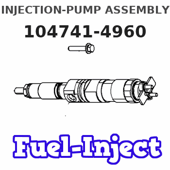
Information injection-pump assembly
BOSCH
F 01G 09W 0AS
f01g09w0as
ZEXEL
104741-4960
1047414960
NISSAN-DIESEL
16700NA01B
16700na01b
Rating:
Compare Prices: .
As an associate, we earn commssions on qualifying purchases through the links below

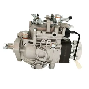
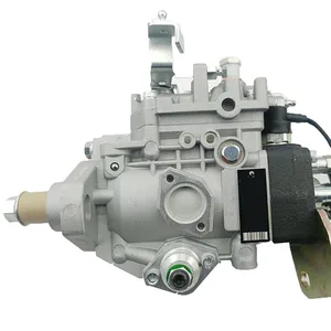
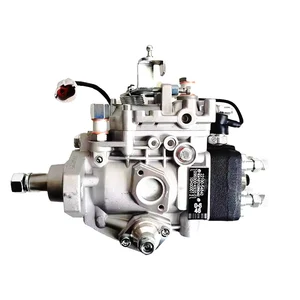
Injection VE Pump VE4/11F1000RNP2611 Compatible For NISSAN QD32 Diesel Fuel Pump 104641-4960 16700-NA01B 16700NA01B
BSZBAS OEM:VE4/11F1000RNP2611 104641-4960 16700-NA01B 16700NA01B || Timely replacement of accessories can extend the service life of equipment || Improving overall efficiency after replacing parts || Please check the product pictures, accessories, and part numbers or OEM numbers before placing an order || If you are unsure, please feel free to ask us before making a purchase
BSZBAS OEM:VE4/11F1000RNP2611 104641-4960 16700-NA01B 16700NA01B || Timely replacement of accessories can extend the service life of equipment || Improving overall efficiency after replacing parts || Please check the product pictures, accessories, and part numbers or OEM numbers before placing an order || If you are unsure, please feel free to ask us before making a purchase

Injection VE Pump VE4/11F1000RNP2611 Compatible For NISSAN QD32 Diesel Fuel Pump 104641-4960 16700-NA01B 16700NA01B
BSZBAS OEM:VE4/11F1000RNP2611 104641-4960 16700-NA01B 16700NA01B || Shell impact resistance || Dual filtration system effectively intercepts impurities and reduces blockage issues || Wide compatibility, meets OEM specifications, allows for direct replacement of parts without the need for modification || After replacement, the throttle response significantly increased and fuel consumption decreased
BSZBAS OEM:VE4/11F1000RNP2611 104641-4960 16700-NA01B 16700NA01B || Shell impact resistance || Dual filtration system effectively intercepts impurities and reduces blockage issues || Wide compatibility, meets OEM specifications, allows for direct replacement of parts without the need for modification || After replacement, the throttle response significantly increased and fuel consumption decreased

104641-4961 16700-NA01B Engine Parts Diesel Fuel Injection Pump,compatible For Engine Excavator
NZMSMS Precision - Engineered Compatibility: The 104641-4961 16700-NA01B Engine Parts Diesel Fuel Injection Pump is meticulously designed to offer a seamless fit for a wide range of excavator engines. Our engineers have thoroughly studied the unique fuel system requirements of various excavator models, ensuring that every dimension, connection interface, and internal component aligns perfectly with the original equipment. Whether you’re a professional mechanic maintaining a fleet of excavators or an || Enhanced Performance for Demanding Jobs: Engineered with cutting - edge technology, this fuel injection pump is built to boost the performance of your excavator engine. Advanced sensors continuously monitor critical engine parameters such as speed, load, and temperature during heavy - duty operations. Paired with intelligent control systems, it makes instant and accurate adjustments to the fuel injection volume and timing. As a result, your excavator engine receives the precise amount of fuel || Rugged and Durable Construction: Excavators operate in some of the harshest environments, and our 104641-4961 16700-NA01B fuel injection pump is built to withstand it all. Constructed from high - quality, heavy - duty materials, the pump housing is made from a robust, corrosion - resistant alloy that can endure exposure to dust, moisture, vibrations, and extreme temperatures. The internal components, including injection nozzles, plungers, and valves, are crafted from premium - grade materials || Fuel - Saving Efficiency: In an industry where fuel costs can significantly impact your bottom line, our fuel injection pump offers an effective solution to optimize fuel consumption for excavator engines. By delivering a precise and consistent fuel supply, it enables the engine to achieve a more efficient fuel - air combustion. The intelligent control system prevents over - injection, ensuring that every drop of fuel is utilized effectively. In a 15,000 - hour field test across multiple || Reliable Operation in All Conditions: No matter the job site environment or operating conditions, this fuel injection pump performs consistently for excavator engines. Engineered to function reliably in extreme cold, sweltering heat, and dusty or wet environments, it features intelligent pressure regulation and monitoring systems that maintain optimal fuel injection pressure within a tight tolerance of ± 0.2 psi. It can also handle variations in fuel quality, ensuring smooth operation even when
NZMSMS Precision - Engineered Compatibility: The 104641-4961 16700-NA01B Engine Parts Diesel Fuel Injection Pump is meticulously designed to offer a seamless fit for a wide range of excavator engines. Our engineers have thoroughly studied the unique fuel system requirements of various excavator models, ensuring that every dimension, connection interface, and internal component aligns perfectly with the original equipment. Whether you’re a professional mechanic maintaining a fleet of excavators or an || Enhanced Performance for Demanding Jobs: Engineered with cutting - edge technology, this fuel injection pump is built to boost the performance of your excavator engine. Advanced sensors continuously monitor critical engine parameters such as speed, load, and temperature during heavy - duty operations. Paired with intelligent control systems, it makes instant and accurate adjustments to the fuel injection volume and timing. As a result, your excavator engine receives the precise amount of fuel || Rugged and Durable Construction: Excavators operate in some of the harshest environments, and our 104641-4961 16700-NA01B fuel injection pump is built to withstand it all. Constructed from high - quality, heavy - duty materials, the pump housing is made from a robust, corrosion - resistant alloy that can endure exposure to dust, moisture, vibrations, and extreme temperatures. The internal components, including injection nozzles, plungers, and valves, are crafted from premium - grade materials || Fuel - Saving Efficiency: In an industry where fuel costs can significantly impact your bottom line, our fuel injection pump offers an effective solution to optimize fuel consumption for excavator engines. By delivering a precise and consistent fuel supply, it enables the engine to achieve a more efficient fuel - air combustion. The intelligent control system prevents over - injection, ensuring that every drop of fuel is utilized effectively. In a 15,000 - hour field test across multiple || Reliable Operation in All Conditions: No matter the job site environment or operating conditions, this fuel injection pump performs consistently for excavator engines. Engineered to function reliably in extreme cold, sweltering heat, and dusty or wet environments, it features intelligent pressure regulation and monitoring systems that maintain optimal fuel injection pressure within a tight tolerance of ± 0.2 psi. It can also handle variations in fuel quality, ensuring smooth operation even when
You can express buy:
USD 388.94
14-06-2025
14-06-2025
Brand New Injection VE Pump VE4/11F1000RNP2611 for NISSAN QD32 Diesel Fuel Pump 104641-4960 16700-NA01B 16700NA01B
USD 433.07
14-06-2025
14-06-2025
Brand New Injection VE Pump VE4/11F1000RNP2611 for NISSAN QD32 Diesel Fuel Pump 104641-4960 16700-NA01B 16700NA01B
USD 405.27
14-06-2025
14-06-2025
Brand New Injection VE Pump VE4/11F1000RNP2611 for NISSAN QD32 Diesel Fuel Pump 104641-4960 16700-NA01B 16700NA01B
Images:
USD 406.7

[19-May-2025]
USD 437.32

[14-Jun-2025]
USD 426.92

[19-May-2025]
USD 411.32

[13-May-2025]
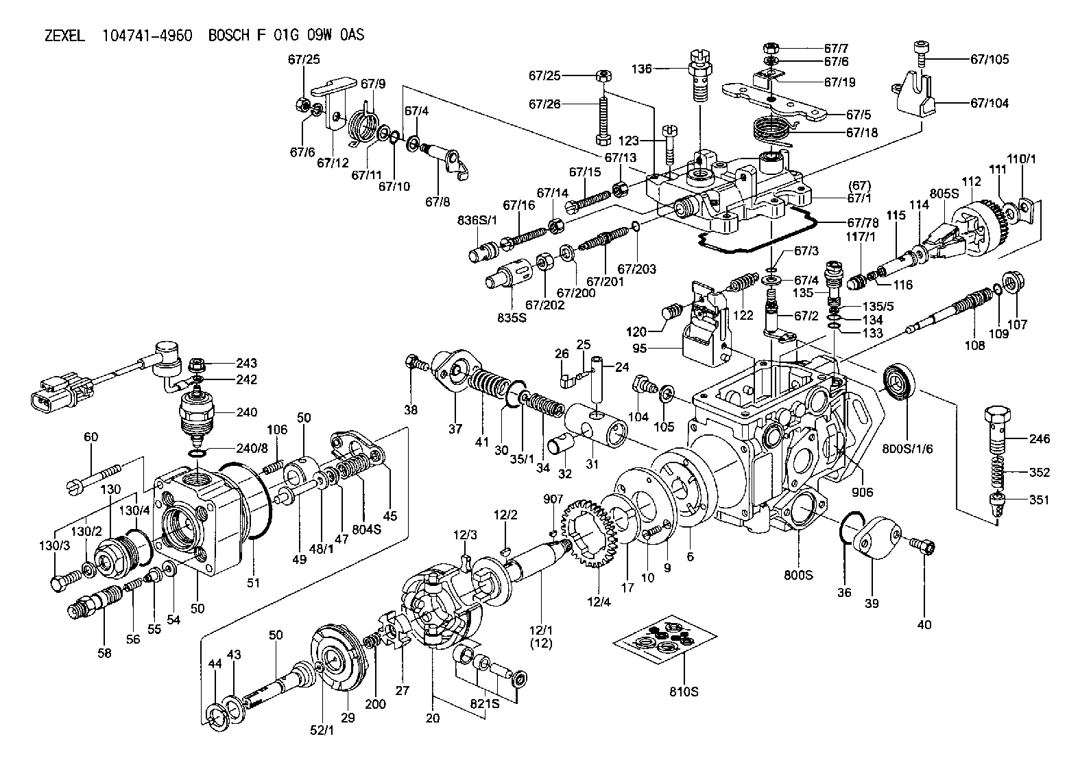
Components :
| 0. | INJECTION-PUMP ASSEMBLY | 104741-4960 |
| 1. | _ | |
| 2. | FUEL INJECTION PUMP | |
| 3. | NUMBER PLATE | |
| 4. | _ | |
| 5. | CAPSULE | |
| 6. | ADJUSTING DEVICE | |
| 7. | NOZZLE AND HOLDER ASSY | 105148-1221 |
| 8. | Nozzle and Holder | |
| 9. | Open Pre:MPa(Kqf/cm2) | 9.8(100) |
| 10. | NOZZLE-HOLDER | 105078-0050 |
| 11. | NOZZLE | 105007-1210 |
Scheme ###:
| 1/6. | [1] | 146601-0900 | PACKING RING |
| 6. | [1] | 146100-0420 | SUPPLY PUMP |
| 9. | [1] | 146103-0100 | COVER |
| 10. | [2] | 139104-0000 | FLAT-HEAD SCREW |
| 12. | [1] | 146200-0020 | DRIVE SHAFT |
| 12/1. | [1] | 146200-0000 | DRIVE SHAFT |
| 12/2. | [1] | 146201-0000 | WOODRUFF KEY |
| 12/3. | [2] | 146202-0100 | DAMPER |
| 12/4. | [1] | 146203-0000 | TOOTHED GEAR |
| 17. | [1] | 146204-0000 | PLAIN WASHER |
| 20. | [1] | 146210-2320 | ROLLER SET |
| 24. | [1] | 146303-0100 | BEARING PIN |
| 25. | [1] | 146304-0000 | BEARING PIN |
| 26. | [1] | 146305-0000 | CLAMPING BAND |
| 27. | [1] | 146205-0000 | SLOTTED WASHER |
| 29. | [1] | 146220-4520 | CAM PLATE |
| 30. | [1] | 146600-0800 | O-RING |
| 31. | [1] | 146311-5420 | PUMP PLUNGER |
| 32. | [1] | 146301-0000 | SLIDING PIECE |
| 34. | [1] | 146312-5200 | COMPRESSION SPRING |
| 34B. | [1] | 146312-6000 | COMPRESSION SPRING |
| 34C. | [1] | 146312-6800 | COMPRESSION SPRING |
| 35/1. | [1] | 146690-3200 | SHIM |
| 35/1. | [1] | 146690-3300 | SHIM |
| 35/1. | [1] | 146690-3400 | SHIM |
| 35/1. | [1] | 146690-3500 | SHIM |
| 35/1. | [1] | 146690-4100 | SHIM |
| 35/1. | [1] | 146690-4200 | SHIM |
| 35/1. | [1] | 146690-4300 | SHIM |
| 36. | [1] | 146600-0800 | O-RING |
| 37. | [1] | 146310-4020 | COVER |
| 38. | [2] | 146620-5000 | BLEEDER SCREW |
| 39. | [1] | 146310-5100 | COVER |
| 40. | [2] | 146620-5000 | BLEEDER SCREW |
| 41. | [1] | 146312-5300 | COMPRESSION SPRING |
| 43. | [1] | 146230-0000 | SHIM |
| 44. | [1] | 146230-0100 | PLAIN WASHER |
| 45. | [1] | 146231-0001 | SLOTTED WASHER |
| 47. | [2] | 146233-0000 | SLOTTED WASHER |
| 48/1. | [1] | 146603-0100 | SHIM |
| 48/1. | [1] | 146603-0200 | SHIM |
| 48/1. | [1] | 146603-0300 | SHIM |
| 48/1. | [1] | 146603-0400 | SHIM |
| 48/1. | [1] | 146690-1400 | SHIM |
| 48/1. | [1] | 146690-1500 | SHIM |
| 48/1. | [1] | 146690-1600 | SHIM |
| 48/1. | [1] | 146690-1700 | SHIM |
| 48/1. | [1] | 146690-1800 | SHIM |
| 49. | [2] | 146234-0600 | GUIDE PIN |
| 50. | [1] | 146401-4220 | HYDRAULIC HEAD |
| 50. | [1] | 146401-4220 | HYDRAULIC HEAD |
| 50. | [1] | 146401-4220 | HYDRAULIC HEAD |
| 51. | [1] | 146600-0000 | O-RING |
| 52/1. | [1] | 146420-0700 | SHIM |
| 52/1. | [1] | 146420-0800 | SHIM |
| 52/1. | [1] | 146420-0900 | SHIM |
| 52/1. | [1] | 146420-1000 | SHIM |
| 52/1. | [1] | 146420-1100 | SHIM |
| 52/1. | [1] | 146420-1200 | SHIM |
| 52/1. | [1] | 146420-1300 | SHIM |
| 52/1. | [1] | 146420-1400 | SHIM |
| 52/1. | [1] | 146420-1500 | SHIM |
| 52/1. | [1] | 146420-1600 | SHIM |
| 52/1. | [1] | 146420-1700 | SHIM |
| 52/1. | [1] | 146420-1800 | SHIM |
| 52/1. | [1] | 146420-1900 | SHIM |
| 52/1. | [1] | 146420-2000 | SHIM |
| 52/1. | [1] | 146420-2100 | SHIM |
| 52/1. | [1] | 146420-2200 | SHIM |
| 52/1. | [1] | 146420-2400 | SHIM |
| 52/1. | [1] | 146420-2500 | SHIM |
| 52/1. | [1] | 146420-2600 | SHIM |
| 52/1. | [1] | 146420-2700 | SHIM |
| 52/1. | [1] | 146420-2800 | SHIM |
| 52/1. | [1] | 146420-2900 | SHIM |
| 52/1. | [1] | 146420-3000 | SHIM |
| 52/1. | [1] | 146420-3100 | SHIM |
| 52/1. | [1] | 146420-3200 | SHIM |
| 52/1. | [1] | 146420-3300 | SHIM |
| 52/1. | [1] | 146420-3400 | SHIM |
| 52/1. | [1] | 146420-3500 | SHIM |
| 52/1. | [1] | 146420-3600 | SHIM |
| 52/1. | [1] | 146420-3700 | SHIM |
| 52/1. | [1] | 146420-3800 | SHIM |
| 52/1. | [1] | 146420-3900 | SHIM |
| 52/1. | [1] | 146420-4000 | SHIM |
| 52/1. | [1] | 146420-4100 | SHIM |
| 54. | [4] | 146433-0100 | GASKET |
| 55. | [4] | 146430-0320 | DELIVERY-VALVE ASSEMBLY |
| 56. | [4] | 146432-0200 | COMPRESSION SPRING |
| 58. | [4] | 146440-0720 | FITTING |
| 60. | [4] | 139106-0100 | FLAT-HEAD SCREW |
| 67. | [1] | 146822-0220 | GOVERNOR COVER |
| 67/1. | [1] | 146805-2120 | GOVERNOR COVER |
| 67/2. | [1] | 146515-0320 | CONTROL SHAFT |
| 67/3. | [1] | 146600-0100 | O-RING |
| 67/4. | [2] | 139310-0200 | PLAIN WASHER |
| 67/4. | [2] | 139310-0200 | PLAIN WASHER |
| 67/5. | [1] | 146530-0000 | CONTROL LEVER |
| 67/5B. | [1] | 146530-0100 | CONTROL LEVER |
| 67/5C. | [1] | 146832-1500 | CONTROL LEVER |
| 67/5D. | [1] | 146832-1600 | CONTROL LEVER |
| 67/6. | [2] | 014110-6440 | LOCKING WASHER |
| 67/6. | [2] | 014110-6440 | LOCKING WASHER |
| 67/7. | [1] | 013020-6040 | UNION NUT |
| 67/8. | [1] | 146515-1820 | LEVER SHAFT |
| 67/9. | [1] | 146592-0400 | COILED SPRING |
| 67/10. | [1] | 146600-0200 | O-RING |
| 67/11. | [1] | 146602-0100 | PLAIN WASHER |
| 67/12. | [1] | 146540-4000 | CONTROL LEVER |
| 67/12B. | [1] | 146540-4100 | CONTROL LEVER |
| 67/13. | [1] | 146621-1700 | UNION NUT |
| 67/14. | [1] | 146621-1700 | UNION NUT |
| 67/15. | [1] | 146526-2800 | BLEEDER SCREW |
| 67/16. | [1] | 146526-6400 | BLEEDER SCREW |
| 67/18. | [1] | 146594-0600 | COILED SPRING |
| 67/19. | [1] | 146541-0000 | ANGLE PIECE |
| 67/25. | [2] | 013020-6040 | UNION NUT |
| 67/25. | [2] | 013020-6040 | UNION NUT |
| 67/26. | [1] | 139006-0200 | BLEEDER SCREW |
| 67/78. | [1] | 146600-4400 | SEAL RING |
| 67/104. | [1] | 146936-1100 | BRACKET |
| 67/105. | [1] | 010206-1040 | HEX-SOCKET-HEAD CAP SCREW |
| 67/200. | [1] | 139308-0300 | PLAIN WASHER |
| 67/201. | [1] | 146545-3400 | THREADED PIN |
| 67/201B. | [1] | 146545-3500 | THREADED PIN |
| 67/201C. | [1] | 146545-3600 | THREADED PIN |
| 67/202. | [1] | 139208-0900 | UNION NUT |
| 67/203. | [1] | 146600-1200 | O-RING |
| 95. | [1] | 146891-1820 | FULCRUM LEVER |
| 104. | [2] | 146568-0000 | SLOTTED SPRING PIN |
| 105. | [2] | 026508-1140 | GASKET |
| 106. | [2] | 146588-0500 | COILED SPRING |
| 107. | [1] | 146569-0300 | UNION NUT |
| 108. | [1] | 146570-0420 | GOVERNOR SHAFT |
| 109. | [1] | 146600-0400 | O-RING |
| 110/1. | [1] | 146571-0000 | SHIM |
| 110/1. | [1] | 146571-0100 | SHIM |
| 110/1. | [1] | 146571-0200 | SHIM |
| 110/1. | [1] | 146571-0300 | SHIM |
| 110/1. | [1] | 146571-0400 | SHIM |
| 111. | [1] | 146602-0600 | PLAIN WASHER |
| 112. | [1] | 146572-0020 | FLYWEIGHT ASSEMBLY |
| 114. | [1] | 146602-2600 | PLAIN WASHER |
| 115. | [1] | 146976-2900 | SLIDING SLEEVE |
| 116. | [1] | 146576-0400 | CAP |
| 117/1. | [1] | 146877-1020 | PLUG |
| 117/1. | [1] | 146877-1120 | PLUG |
| 117/1. | [1] | 146877-1220 | PLUG |
| 117/1. | [1] | 146877-1320 | PLUG |
| 117/1. | [1] | 146877-1420 | PLUG |
| 117/1. | [1] | 146877-1520 | PLUG |
| 117/1. | [1] | 146877-1620 | PLUG |
| 117/1. | [1] | 146877-1720 | PLUG |
| 117/1. | [1] | 146877-1820 | PLUG |
| 117/1. | [1] | 146877-1920 | PLUG |
| 117/1. | [1] | 146877-2020 | PLUG |
| 117/1. | [1] | 146877-2120 | PLUG |
| 117/1. | [1] | 146877-2220 | PLUG |
| 117/1. | [1] | 146877-2320 | PLUG |
| 117/1. | [1] | 146877-2420 | PLUG |
| 117/1. | [1] | 146877-2520 | PLUG |
| 117/1. | [1] | 146877-2620 | PLUG |
| 120. | [1] | 146579-2720 | RETAINING PIN |
| 122. | [1] | 146580-4100 | GOVERNOR SPRING |
| 123. | [4] | 139106-0200 | FLAT-HEAD SCREW |
| 130. | [1] | 146421-0020 | CAPSULE |
| 130/2. | [1] | 026508-1140 | GASKET |
| 130/3. | [1] | 146422-0000 | BLEEDER SCREW |
| 130/4. | [1] | 146600-0500 | O-RING |
| 133. | [1] | 146600-0600 | O-RING |
| 134. | [1] | 146600-0700 | O-RING |
| 135. | [1] | 146110-0520 | CONTROL VALVE |
| 135/5. | [1] | 146114-0000 | SPRING WASHER |
| 136. | [1] | 146120-0120 | OVER FLOW VALVE |
| 200. | [1] | 146206-0100 | COILED SPRING |
| 240. | [1] | 146650-0720 | PULLING ELECTROMAGNET |
| 240/8. | [1] | 146600-1700 | O-RING |
| 242. | [1] | 146662-8320 | WIRE |
| 243. | [1] | 146621-4901 | UNION NUT |
| 246. | [1] | 027412-2440 | EYE BOLT |
| 351. | [1] | 146125-0101 | FILTER |
| 352. | [1] | 146125-0200 | COILED SPRING |
| 800S. | [1] | 146019-8820 | PUMP HOUSING |
| 800S/1/6. | [1] | 146601-0900 | PACKING RING |
| 804S. | [1] | 146232-1520 | COMPRESSION SPRING |
| 805S. | [1] | 146574-0320 | PARTS SET |
| 810S. | [1] | 146600-1120 | REPAIR SET |
| 821S. | [1] | 146210-5720 | ROLLER SET |
| 835S. | [1] | 146598-1000 | CAP |
| 836S/1. | [1] | 146598-0600 | CAP |
| 836S/1. | [1] | 146598-0700 | CAP |
| 836S/1. | [1] | 146598-0800 | CAP |
| 836S/1. | [1] | 146598-0900 | CAP |
| 906. | [1] | 146984-8000 | NAMEPLATE |
| 907. | [1] | 025803-1640 | WOODRUFF KEY |
Include in #2:
104741-4960
as INJECTION-PUMP ASSEMBLY
Cross reference number
BOSCH
F 01G 09W 0AS
f01g09w0as
ZEXEL
104741-4960
1047414960
NISSAN-DIESEL
16700NA01B
16700na01b
Zexel num
Bosch num
Firm num
Name
Calibration Data:
Adjustment conditions
Test oil
1404 Test oil ISO4113orSAEJ967d
1404 Test oil ISO4113orSAEJ967d
Test oil temperature
degC
45
45
50
Nozzle
105780-0060
Bosch type code
NP-DN0SD1510
Nozzle holder
105780-2150
Opening pressure
MPa
13
13
13.3
Opening pressure
kgf/cm2
133
133
136
Injection pipe
157805-7320
Injection pipe
Inside diameter - outside diameter - length (mm) mm 2-6-450
Inside diameter - outside diameter - length (mm) mm 2-6-450
Joint assembly
157641-4720
Tube assembly
157641-4020
Transfer pump pressure
kPa
20
20
20
Transfer pump pressure
kgf/cm2
0.2
0.2
0.2
Direction of rotation (viewed from drive side)
Right R
Right R
Injection timing adjustment
Pump speed
r/min
900
900
900
Average injection quantity
mm3/st.
54
53.5
54.5
Difference in delivery
mm3/st.
4.5
Basic
*
Oil temperature
degC
50
48
52
Injection timing adjustment_02
Pump speed
r/min
400
400
400
Average injection quantity
mm3/st.
50
50
50
Oil temperature
degC
48
46
50
Injection timing adjustment_03
Pump speed
r/min
500
500
500
Average injection quantity
mm3/st.
50.6
46.6
54.6
Oil temperature
degC
48
46
50
Injection timing adjustment_04
Pump speed
r/min
750
750
750
Average injection quantity
mm3/st.
52.1
52.1
52.1
Oil temperature
degC
50
48
52
Injection timing adjustment_05
Pump speed
r/min
900
900
900
Average injection quantity
mm3/st.
54
53
55
Difference in delivery
mm3/st.
5
Basic
*
Oil temperature
degC
50
48
52
Injection timing adjustment_06
Pump speed
r/min
1000
1000
1000
Average injection quantity
mm3/st.
52.9
49.4
56.4
Oil temperature
degC
50
48
52
Injection quantity adjustment
Pump speed
r/min
1245
1245
1245
Average injection quantity
mm3/st.
8
6
10
Difference in delivery
mm3/st.
2.5
Basic
*
Oil temperature
degC
50
48
52
Injection quantity adjustment_02
Pump speed
r/min
1400
1400
1400
Average injection quantity
mm3/st.
5
Oil temperature
degC
50
48
52
Injection quantity adjustment_03
Pump speed
r/min
1245
1245
1245
Average injection quantity
mm3/st.
8
4.5
11.5
Basic
*
Oil temperature
degC
50
48
52
Governor adjustment
Pump speed
r/min
375
375
375
Average injection quantity
mm3/st.
8
6
10
Difference in delivery
mm3/st.
2
Basic
*
Oil temperature
degC
48
46
50
Governor adjustment_02
Pump speed
r/min
375
375
375
Average injection quantity
mm3/st.
8
5.5
10.5
Difference in delivery
mm3/st.
2.5
Basic
*
Oil temperature
degC
48
46
50
Timer adjustment
Pump speed
r/min
100
100
100
Average injection quantity
mm3/st.
56.9
51.9
61.9
Basic
*
Oil temperature
degC
48
46
50
Remarks
Full
Full
Timer adjustment_02
Pump speed
r/min
100
100
100
Average injection quantity
mm3/st.
56.9
51.9
61.9
Basic
*
Oil temperature
degC
48
46
50
Remarks
Full
Full
Speed control lever angle
Pump speed
r/min
375
375
375
Average injection quantity
mm3/st.
0
0
0
Oil temperature
degC
48
46
50
Remarks
Magnet OFF at idling position
Magnet OFF at idling position
0000000901
Pump speed
r/min
900
900
900
Overflow quantity
cm3/min
440
310
570
Oil temperature
degC
50
48
52
Stop lever angle
Pump speed
r/min
900
900
900
Pressure
kPa
549
520
578
Pressure
kgf/cm2
5.6
5.3
5.9
Basic
*
Oil temperature
degC
50
48
52
Stop lever angle_02
Pump speed
r/min
900
900
900
Pressure
kPa
549
510
588
Pressure
kgf/cm2
5.6
5.2
6
Basic
*
Oil temperature
degC
50
48
52
Stop lever angle_03
Pump speed
r/min
1000
1000
1000
Pressure
kPa
588
549
627
Pressure
kgf/cm2
6
5.6
6.4
Oil temperature
degC
50
48
52
0000001101
Pump speed
r/min
900
900
900
Timer stroke
mm
2.3
2.1
2.5
Basic
*
Oil temperature
degC
50
48
52
_02
Pump speed
r/min
800
800
800
Timer stroke
mm
1.8
1.3
2.3
Oil temperature
degC
50
48
52
_03
Pump speed
r/min
900
900
900
Timer stroke
mm
2.3
2
2.6
Basic
*
Oil temperature
degC
50
48
52
_04
Pump speed
r/min
1000
1000
1000
Timer stroke
mm
2.9
2.4
3.4
Oil temperature
degC
50
48
52
0000001201
Max. applied voltage
V
8
8
8
Test voltage
V
13
12
14
0000001401
Pump speed
r/min
900
900
900
Average injection quantity
mm3/st.
32
31.5
32.5
Timer stroke TA
mm
1.6
1.4
1.8
Timer stroke variation dT
mm
0.7
0.7
0.7
Basic
*
Oil temperature
degC
50
48
52
_02
Pump speed
r/min
900
900
900
Average injection quantity
mm3/st.
32
31
33
Timer stroke TA
mm
1.6
1.3
1.9
Timer stroke variation dT
mm
0.7
0.7
0.7
Basic
*
Oil temperature
degC
50
48
52
_03
Pump speed
r/min
900
900
900
Average injection quantity
mm3/st.
18
15.5
20.5
Timer stroke TA
mm
0.9
0.4
1.4
Timer stroke variation dT
mm
1.4
1.4
1.4
Oil temperature
degC
50
48
52
Timing setting
K dimension
mm
3.3
3.2
3.4
KF dimension
mm
5.62
5.52
5.72
MS dimension
mm
1.8
1.7
1.9
Pre-stroke
mm
0.1
0.08
0.12
Control lever angle alpha
deg.
25
21
29
Control lever angle beta
deg.
28
23
33
Test data Ex:
0000001801 STOP LEVER ADJUSTMENT
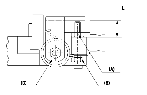
Adjustment of the stop lever
Adjust adjusting bolt (B) so that the starting injection quantity is within the standard.
Fix using nut.
(A) Adjusting nut
(C) Starting injection quantity adjusting lever
----------
----------
L=15.0~18.5mm
----------
----------
L=15.0~18.5mm
Information:
Refer to attached Rework Procedure.
SERVICE CLAIM ALLOWANCES
Product smu/age whichever comes first Caterpillar Dealer Suggested Customer Suggested
Parts % Labor Hrs% Parts % Labor Hrs% Parts % Labor Hrs%
*******Group 1*******
0-2000 hrs,
0-12 mo 100.0% 100.0% 0.0% 0.0% 0.0% 0.0%
2001-5000 hrs,
13-18 mo 100.0% 50.0% 0.0% 0.0% 0.0% 50.0%
5001-8000 hrs,
19-24 mo 100.0% 30.0% 0.0% 0.0% 0.0% 70.0%
This is a 4.0-hour job for Group 1
Product smu/age whichever comes first Caterpillar Dealer Suggested Customer Suggested
Parts % Labor Hrs% Parts % Labor Hrs% Parts % Labor Hrs%
*******Group 2*******
0-2000 hrs,
0-12 mo 100.0% 100.0% 0.0% 0.0% 0.0% 0.0%
2001-5000 hrs,
13-18 mo 100.0% 50.0% 0.0% 0.0% 0.0% 50.0%
5001-8000 hrs,
19-24 mo 100.0% 30.0% 0.0% 0.0% 0.0% 70.0%
This is a 4.0-hour job for Group 2
PARTS DISPOSITION
removed java code "affectDisposition"commented on Chints October 12 2006 Chints w.r.t CM000343756-->
Handle the parts in accordance with your Warranty Bulletin on warranty parts handling.
Rework Procedure
For the following units listed remove (6) 207-5248 Injector Rocker Arms, and replace with (6) 278-1365 Injector Rocker Arms.
For proper ?Disassembly & Assembly? instructions of the injector rocker arms please refer to the following Publications in SIS Web. (SENR9832-06 Testing & Adjusting-Finding Top Dead Center Position for No. 1 Piston), (SENR9832-06 Testing & Adjusting-Electronic Unit Injector Adjusting & Setting), and (SENR9832-06 Testing & Adjusting-Engine Valve Lash Inspect/Adjust).
Note: It is important that while installing the 278-1365 Injector Rocker Arms, that the engine is in the proper position (Top Dead Center and 180 degrees out) so the Injector Rocker Arms are properly adjusted and set. It is also important that during the installation of the Injector Rocker Arms that the Exhaust Valve, and Intake Valve lash settings be inspected and if needed re-set to factory specifications.
Note: During the rework process please inspect the 6I-0901 Rocker Arm Shafts for any signs of misalignment of the stud mounting holes, wear, damage, fretting etc. If damage is found to the shaft or if fretting or damage is found with any of the through bolt/stud mounting holes, the shaft is to be replaced, and reported against this service letter as contingent damage.