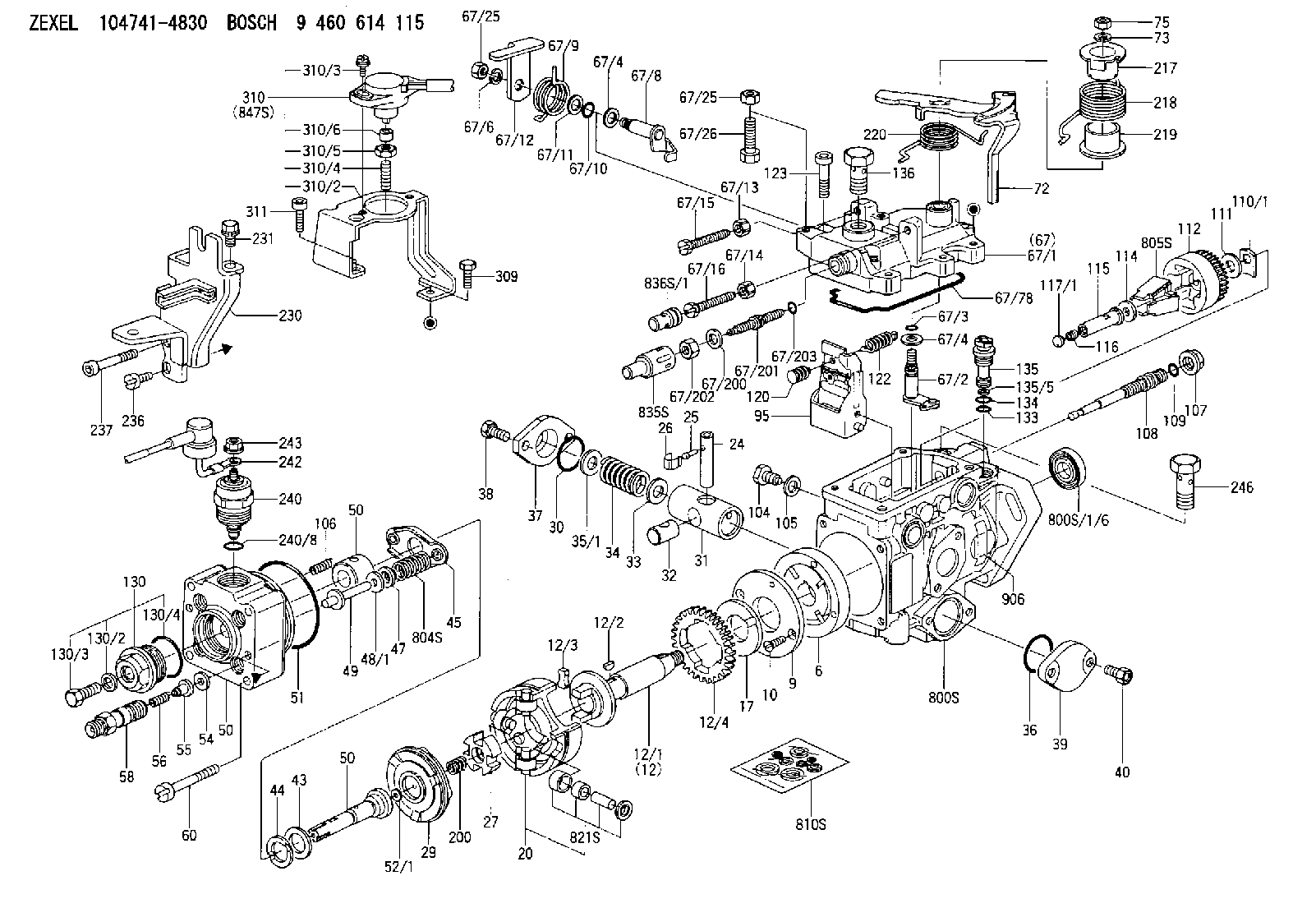
Information injection-pump assembly
BOSCH
9 460 614 115
9460614115
ZEXEL
104741-4830
1047414830
NISSAN-DIESEL
1670084K20
1670084k20

Rating:
Components :
| 0. | INJECTION-PUMP ASSEMBLY | 104741-4830 |
| 1. | _ | |
| 2. | FUEL INJECTION PUMP | 104641-4830 |
| 3. | NUMBER PLATE | |
| 4. | _ | |
| 5. | CAPSULE | |
| 6. | ADJUSTING DEVICE | |
| 7. | NOZZLE AND HOLDER ASSY | 105148-1221 |
| 8. | Nozzle and Holder | 16600-63G01 |
| 9. | Open Pre:MPa(Kqf/cm2) | 9.8{100} |
| 10. | NOZZLE-HOLDER | 105078-0050 |
| 11. | NOZZLE | 105007-1210 |
Scheme ###:
| 1/6. | [1] | 146601-0900 | PACKING RING |
| 6. | [1] | 146100-0020 | SUPPLY PUMP |
| 9. | [1] | 146103-0000 | COVER |
| 10. | [2] | 139104-0000 | FLAT-HEAD SCREW |
| 12. | [1] | 146200-0020 | DRIVE SHAFT |
| 12/1. | [1] | 146200-0000 | DRIVE SHAFT |
| 12/2. | [1] | 146201-0000 | WOODRUFF KEY |
| 12/3. | [2] | 146202-0100 | DAMPER |
| 12/4. | [1] | 146203-0000 | TOOTHED GEAR |
| 17. | [1] | 146204-0000 | PLAIN WASHER |
| 20. | [1] | 146210-1720 | ROLLER SET |
| 24. | [1] | 146303-0100 | BEARING PIN |
| 25. | [1] | 146304-0000 | BEARING PIN |
| 26. | [1] | 146305-0000 | CLAMPING BAND |
| 27. | [1] | 146205-0000 | SLOTTED WASHER |
| 29. | [1] | 146220-4520 | CAM PLATE |
| 30. | [1] | 146600-0800 | O-RING |
| 31. | [1] | 146300-0300 | PUMP PLUNGER |
| 32. | [1] | 146301-0000 | SLIDING PIECE |
| 33. | [1] | 146603-0700 | SHIM D17.5&7.5T0.60 |
| 34. | [1] | 146302-3300 | COMPRESSION SPRING |
| 34B. | [1] | 146302-9600 | COMPRESSION SPRING |
| 34C. | [1] | 146302-3400 | COMPRESSION SPRING |
| 35/1. | [0] | 146603-0700 | SHIM D17.5&7.5T0.60 |
| 35/1. | [0] | 146603-0800 | SHIM D17.5&7.5T0.70 |
| 35/1. | [0] | 146603-0900 | SHIM D17.5&7.5T0.90 |
| 35/1. | [0] | 146603-1000 | SHIM D17.5&7.5T1.00 |
| 35/1. | [0] | 146603-1100 | SHIM D17.5&7.5T1.20 |
| 35/1. | [0] | 146603-3600 | SHIM D17.5&7.5T2.40 |
| 36. | [1] | 146600-0800 | O-RING |
| 37. | [1] | 146310-0700 | COVER |
| 38. | [2] | 146620-5000 | BLEEDER SCREW |
| 39. | [1] | 146310-5100 | COVER |
| 40. | [2] | 146620-5000 | BLEEDER SCREW |
| 43. | [1] | 146230-0000 | SHIM |
| 44. | [1] | 146230-0100 | PLAIN WASHER |
| 45. | [1] | 146231-0001 | SLOTTED WASHER |
| 47. | [2] | 146233-0000 | SLOTTED WASHER |
| 48/1. | [1] | 146603-0000 | SHIM D17.0&5.2T0.50 |
| 48/1. | [1] | 146603-0100 | SHIM D17.0&5.2T0.80 |
| 48/1. | [1] | 146603-0200 | SHIM D17.0&5.2T1.00 |
| 48/1. | [1] | 146603-0300 | SHIM D17.0&5.2T1.20 |
| 48/1. | [1] | 146603-0400 | SHIM D17.0&5.2T1.50 |
| 48/1. | [1] | 146603-0500 | SHIM D17.0&5.2T1.80 |
| 48/1. | [1] | 146603-0600 | SHIM D17.0&5.2T2.00 |
| 48/1. | [1] | 146690-1400 | SHIM D17&5.2T0.9 |
| 48/1. | [1] | 146690-1500 | SHIM D17&5.2T1.1 |
| 48/1. | [1] | 146690-1600 | SHIM D17&5.2T1.3 |
| 48/1. | [1] | 146690-1700 | SHIM D17&5.2T1.4 |
| 48/1. | [1] | 146690-1800 | SHIM D17&5.2T1.6 |
| 48/1. | [1] | 146690-1900 | SHIM D17&5.2T1.7 |
| 48/1. | [1] | 146690-5800 | SHIM D17&5.2T2.1 |
| 48/1. | [1] | 146690-5900 | SHIM D17&5.2T2.2 |
| 48/1. | [1] | 146690-6000 | SHIM D17&5.2T2.3 |
| 48/1. | [1] | 146690-6100 | SHIM D17&5.2T2.4 |
| 48/1. | [1] | 146690-6200 | SHIM D17&5.2T2.5 |
| 48/1. | [1] | 146690-6300 | SHIM D17&5.2T2.6 |
| 48/1. | [1] | 146690-6400 | SHIM D17&5.2T2.7 |
| 48/1. | [1] | 146690-6500 | SHIM D17&5.2T2.8 |
| 48/1. | [1] | 146690-6600 | SHIM D17&5.2T2.9 |
| 48/1. | [1] | 146690-6700 | SHIM D17&5.2T3.0 |
| 48/1. | [1] | 146690-6800 | SHIM D17&5.2T3.1 |
| 48/1. | [1] | 146690-6900 | SHIM D17&5.2T3.2 |
| 48/1. | [1] | 146690-7000 | SHIM D17&5.2T3.3 |
| 48/1. | [1] | 146690-7100 | SHIM D17&5.2T3.4 |
| 48/1. | [1] | 146690-7200 | SHIM D17&5.2T0.4 |
| 48/1. | [1] | 146690-7300 | SHIM D17&5.2T0.6 |
| 48/1. | [1] | 146690-7400 | SHIM D17&5.2T0.7 |
| 48/1. | [1] | 146690-7500 | SHIM D17&5.2T1.9 |
| 48/1. | [1] | 146690-7800 | SHIM D17&5.2T0.2 |
| 49. | [2] | 146234-0600 | GUIDE PIN |
| 50. | [1] | 146401-4220 | HYDRAULIC HEAD |
| 50. | [1] | 146401-4220 | HYDRAULIC HEAD |
| 50. | [1] | 146401-4220 | HYDRAULIC HEAD |
| 51. | [1] | 146600-0000 | O-RING |
| 52/1. | [1] | 146420-0000 | SHIM D9.5&3.0T1.90 |
| 52/1. | [1] | 146420-0100 | SHIM D9.5&3.0T1.92 |
| 52/1. | [1] | 146420-0200 | SHIM D9.5&3.0T1.94 |
| 52/1. | [1] | 146420-0300 | SHIM D9.5&3.0T1.96 |
| 52/1. | [1] | 146420-0400 | SHIM D9.5&3.0T1.98 |
| 52/1. | [1] | 146420-0500 | SHIM D9.5&3.0T2.00 |
| 52/1. | [1] | 146420-0600 | SHIM D9.5&3.0T2.02 |
| 52/1. | [1] | 146420-0700 | SHIM D9.5&3.0T2.04 |
| 52/1. | [1] | 146420-0800 | SHIM D9.5&3.0T2.06 |
| 52/1. | [1] | 146420-0900 | SHIM D9.5&3.0T2.08 |
| 52/1. | [1] | 146420-1000 | SHIM D9.5&3.0T2.10 |
| 52/1. | [1] | 146420-1100 | SHIM D9.5&3.0T2.12 |
| 52/1. | [1] | 146420-1200 | SHIM D9.5&3.0T2.14 |
| 52/1. | [1] | 146420-1300 | SHIM D9.5&3.0T2.16 |
| 52/1. | [1] | 146420-1400 | SHIM D9.5&3.0T2.18 |
| 52/1. | [1] | 146420-1500 | SHIM D9.5&3.0T2.20 |
| 52/1. | [1] | 146420-1600 | SHIM D9.5&3.0T2.22 |
| 52/1. | [1] | 146420-1700 | SHIM D9.5&3.0T2.24 |
| 52/1. | [1] | 146420-1800 | SHIM D9.5&3.0T2.26 |
| 52/1. | [1] | 146420-1900 | SHIM D9.5&3.0T2.28 |
| 52/1. | [1] | 146420-2000 | SHIM D9.5&3.0T2.30 |
| 52/1. | [1] | 146420-2100 | SHIM D9.5&3.0T2.32 |
| 52/1. | [1] | 146420-2200 | SHIM D9.5&3.0T2.34 |
| 52/1. | [1] | 146420-2300 | SHIM D9.5&3.0T2.36 |
| 52/1. | [1] | 146420-2400 | SHIM D9.5&3.0T2.38 |
| 52/1. | [1] | 146420-2500 | SHIM D9.5&3.0T2.40 |
| 52/1. | [1] | 146420-2600 | SHIM D9.5&3.0T2.42 |
| 52/1. | [1] | 146420-2700 | SHIM D9.5&3.0T2.44 |
| 52/1. | [1] | 146420-2800 | SHIM D9.5&3.0T2.46 |
| 52/1. | [1] | 146420-2900 | SHIM D9.5&3.0T2.48 |
| 52/1. | [1] | 146420-3000 | SHIM D9.5&3.0T2.50 |
| 52/1. | [1] | 146420-3100 | SHIM D9.5&3.0T2.52 |
| 52/1. | [1] | 146420-3200 | SHIM D9.5&3.0T2.54 |
| 52/1. | [1] | 146420-3300 | SHIM D9.5&3.0T2.56 |
| 52/1. | [1] | 146420-3400 | SHIM D9.5&3.0T2.58 |
| 52/1. | [1] | 146420-3500 | SHIM D9.5&3.0T2.60 |
| 52/1. | [1] | 146420-3600 | SHIM D9.5&3.0T2.62 |
| 52/1. | [1] | 146420-3700 | SHIM D9.5&3.0T2.64 |
| 52/1. | [1] | 146420-3800 | SHIM D9.5&3.0T2.66 |
| 52/1. | [1] | 146420-3900 | SHIM D9.5&3.0T2.68 |
| 52/1. | [1] | 146420-4000 | SHIM D9.5&3.0T2.70 |
| 52/1. | [1] | 146420-4100 | SHIM D9.5&3.0T2.72 |
| 52/1. | [1] | 146420-4200 | SHIM D9.5&3.0T2.74 |
| 52/1. | [1] | 146420-4300 | SHIM D9.5&3.0T2.76 |
| 52/1. | [1] | 146420-4400 | SHIM D9.5&3.0T2.78 |
| 52/1. | [1] | 146420-4500 | SHIM D9.5&3.0T2.80 |
| 52/1. | [1] | 146420-4600 | SHIM D9.5&3.0T2.82 |
| 52/1. | [1] | 146420-4700 | SHIM D9.5&3.0T2.84 |
| 52/1. | [1] | 146420-4800 | SHIM D9.5&3.0T2.86 |
| 52/1. | [1] | 146420-4900 | SHIM D9.5&3.0T2.88 |
| 52/1. | [1] | 146420-5000 | SHIM D9.5&3.0T2.90 |
| 52/1. | [1] | 146420-5100 | SHIM D9.5&3.0T1.74 |
| 52/1. | [1] | 146420-5200 | SHIM D9.5&3.0T1.76 |
| 52/1. | [1] | 146420-5300 | SHIM D9.5&3.0T1.78 |
| 52/1. | [1] | 146420-5400 | SHIM D9.5&3.0T1.80 |
| 52/1. | [1] | 146420-5500 | SHIM D9.5&3.0T1.82 |
| 52/1. | [1] | 146420-5600 | SHIM D9.5&3.0T1.84 |
| 52/1. | [1] | 146420-5700 | SHIM D9.5&3.0T1.86 |
| 52/1. | [1] | 146420-5800 | SHIM D9.5&3.0T1.88 |
| 54. | [4] | 146433-0100 | GASKET D12&6.4T1.00 |
| 55. | [4] | 146430-0320 | DELIVERY-VALVE ASSEMBLY |
| 56. | [4] | 146432-0200 | COMPRESSION SPRING |
| 58. | [4] | 146440-0720 | FITTING |
| 60. | [3] | 139106-0100 | FLAT-HEAD SCREW |
| 67. | [1] | 146822-0320 | GOVERNOR COVER |
| 67/1. | [1] | 146805-2120 | GOVERNOR COVER |
| 67/2. | [1] | 146515-2520 | CONTROL SHAFT |
| 67/3. | [1] | 146600-0100 | O-RING |
| 67/4. | [2] | 139310-0200 | PLAIN WASHER |
| 67/4. | [2] | 139310-0200 | PLAIN WASHER |
| 67/6. | [1] | 014110-6440 | LOCKING WASHER |
| 67/8. | [1] | 146515-1820 | LEVER SHAFT |
| 67/9. | [1] | 146592-0400 | COILED SPRING |
| 67/10. | [1] | 146600-0200 | O-RING |
| 67/11. | [1] | 146602-0100 | PLAIN WASHER D14&10.1T1.50 |
| 67/12. | [1] | 146540-4000 | CONTROL LEVER |
| 67/12B. | [1] | 146540-4100 | CONTROL LEVER |
| 67/13. | [1] | 146621-1700 | UNION NUT |
| 67/14. | [1] | 146621-1700 | UNION NUT |
| 67/15. | [1] | 146526-2800 | BLEEDER SCREW |
| 67/16. | [1] | 146526-6400 | BLEEDER SCREW |
| 67/25. | [2] | 013020-6040 | UNION NUT M6P1H5 |
| 67/25. | [2] | 013020-6040 | UNION NUT M6P1H5 |
| 67/26. | [1] | 139006-0200 | BLEEDER SCREW |
| 67/78. | [1] | 146600-4400 | SEAL RING |
| 67/200. | [1] | 139308-0300 | PLAIN WASHER |
| 67/201. | [1] | 146545-3400 | THREADED PIN L53.00 |
| 67/201B. | [1] | 146545-3500 | THREADED PIN L55.00 |
| 67/201C. | [1] | 146545-3600 | THREADED PIN L57.00 |
| 67/202. | [1] | 139208-0900 | UNION NUT |
| 67/203. | [1] | 146600-1200 | O-RING |
| 72. | [1] | 146831-0520 | CONTROL LEVER |
| 72B. | [1] | 146831-0620 | CONTROL LEVER |
| 73. | [1] | 014110-6440 | LOCKING WASHER |
| 75. | [1] | 146621-0700 | UNION NUT |
| 95. | [1] | 146871-6720 | FULCRUM LEVER |
| 104. | [2] | 146568-0000 | SLOTTED SPRING PIN |
| 105. | [2] | 026508-1140 | GASKET D11.4&8.2T1 |
| 106. | [2] | 146588-0500 | COILED SPRING |
| 107. | [1] | 146569-0300 | UNION NUT |
| 108. | [1] | 146570-0100 | GOVERNOR SHAFT |
| 109. | [1] | 146600-0400 | O-RING |
| 110/1. | [1] | 146571-0000 | SHIM D20.2&8.3T1.05 |
| 110/1. | [1] | 146571-0100 | SHIM D20.2&8.3T1.25 |
| 110/1. | [1] | 146571-0200 | SHIM D20.2&8.3T1.45 |
| 110/1. | [1] | 146571-0300 | SHIM D20.2&8.3T1.65 |
| 110/1. | [1] | 146571-0400 | SHIM D20.2&8.3T1.85 |
| 110/1. | [1] | 146571-0500 | SHIM D20.2&8.3T1.15 |
| 110/1. | [1] | 146571-0600 | SHIM D20.2&8.3T1.35 |
| 110/1. | [1] | 146571-0700 | SHIM D20.2&8.3T1.55 |
| 110/1. | [1] | 146571-0800 | SHIM D20.2&8.3T1.75 |
| 111. | [1] | 146602-0600 | PLAIN WASHER D20&8.4T1.40 |
| 112. | [1] | 146572-0020 | FLYWEIGHT ASSEMBLY |
| 114. | [1] | 146602-0500 | PLAIN WASHER D17&6.4T1.60 |
| 115. | [1] | 146975-4200 | SLIDING SLEEVE |
| 116. | [1] | 146576-0200 | CAP |
| 117/1. | [1] | 146577-1800 | PLUG L2.10 |
| 117/1. | [1] | 146577-1900 | PLUG L2.30 |
| 117/1. | [1] | 146577-2000 | PLUG L2.50 |
| 117/1. | [1] | 146577-2100 | PLUG L2.70 |
| 117/1. | [1] | 146577-2200 | PLUG L2.90 |
| 117/1. | [1] | 146577-2300 | PLUG L3.10 |
| 117/1. | [1] | 146577-2400 | PLUG L3.30 |
| 117/1. | [1] | 146577-2500 | PLUG L3.50 |
| 117/1. | [1] | 146577-2600 | PLUG L3.70 |
| 117/1. | [1] | 146577-2700 | PLUG L3.90 |
| 117/1. | [1] | 146577-2800 | PLUG L4.10 |
| 117/1. | [1] | 146577-2900 | PLUG L4.30 |
| 117/1. | [1] | 146577-3000 | PLUG L4.50 |
| 117/1. | [1] | 146577-3100 | PLUG L4.70 |
| 117/1. | [1] | 146577-3200 | PLUG L4.90 |
| 117/1. | [1] | 146577-3300 | PLUG L5.10 |
| 117/1. | [1] | 146577-6700 | PLUG L2.2 |
| 117/1. | [1] | 146577-6800 | PLUG L2.4 |
| 117/1. | [1] | 146577-6900 | PLUG L2.6 |
| 117/1. | [1] | 146577-7000 | PLUG L2.8 |
| 117/1. | [1] | 146577-7100 | PLUG L3.0 |
| 117/1. | [1] | 146577-7200 | PLUG L3.2 |
| 117/1. | [1] | 146577-7300 | PLUG L3.4 |
| 117/1. | [1] | 146577-7400 | PLUG L3.6 |
| 117/1. | [1] | 146577-7500 | PLUG L3.8 |
| 117/1. | [1] | 146577-7600 | PLUG L4.0 |
| 117/1. | [1] | 146577-7700 | PLUG L4.2 |
| 117/1. | [1] | 146577-7800 | PLUG L4.4 |
| 117/1. | [1] | 146577-7900 | PLUG L4.6 |
| 117/1. | [1] | 146577-8000 | PLUG L4.8 |
| 117/1. | [1] | 146577-8100 | PLUG L5.0 |
| 117/1. | [1] | 146877-0000 | PLUG L5.2 |
| 117/1. | [1] | 146877-0100 | PLUG L5.3 |
| 117/1. | [1] | 146877-0200 | PLUG L5.4 |
| 117/1. | [1] | 146877-0300 | PLUG L5.5 |
| 117/1. | [1] | 146877-4700 | PLUG |
| 117/1. | [1] | 146877-4800 | PLUG |
| 117/1. | [1] | 146877-4900 | PLUG |
| 117/1. | [1] | 146877-5000 | PLUG |
| 120. | [1] | 146879-1420 | RETAINING PIN |
| 122. | [1] | 146580-3900 | GOVERNOR SPRING |
| 123. | [4] | 139106-0200 | FLAT-HEAD SCREW |
| 130. | [1] | 146421-0020 | CAPSULE |
| 130/2. | [1] | 026508-1140 | GASKET D11.4&8.2T1 |
| 130/3. | [1] | 146422-0000 | BLEEDER SCREW |
| 130/4. | [1] | 146600-0500 | O-RING |
| 133. | [1] | 146600-0600 | O-RING |
| 134. | [1] | 146600-0700 | O-RING |
| 135. | [1] | 146110-0220 | CONTROL VALVE |
| 135/5. | [1] | 146114-0000 | SPRING WASHER |
| 136. | [1] | 146120-0020 | OVER FLOW VALVE |
| 200. | [1] | 146206-0100 | COILED SPRING |
| 217. | [1] | 146541-3100 | SLOTTED WASHER |
| 218. | [1] | 146592-1300 | COILED SPRING |
| 219. | [1] | 146541-3000 | BUSHING |
| 220. | [1] | 146587-7200 | COILED SPRING |
| 230. | [1] | 146934-1120 | BRACKET |
| 231. | [1] | 139006-4600 | BLEEDER SCREW |
| 236. | [1] | 139006-4800 | BLEEDER SCREW |
| 237. | [1] | 146620-0200 | HEX-SOCKET-HEAD CAP SCREW |
| 240. | [1] | 146650-0720 | PULLING ELECTROMAGNET |
| 240/8. | [1] | 146600-1700 | O-RING |
| 242. | [1] | 146658-6120 | WIRE |
| 243. | [1] | 146621-4901 | UNION NUT |
| 246. | [1] | 027412-2440 | EYE BOLT |
| 309. | [1] | 139006-4600 | BLEEDER SCREW |
| 310. | [1] | 146684-8820 | POTENTCIOMETER |
| 310/2. | [1] | 146926-0700 | BRACKET |
| 310/3. | [2] | 139104-0400 | FLAT-HEAD SCREW |
| 310/4. | [1] | 146620-2900 | FLAT-HEAD SCREW |
| 310/5. | [1] | 146621-0500 | UNION NUT |
| 310/6. | [1] | 146614-2300 | JOINT CONNECTION |
| 311. | [2] | 010206-1040 | HEX-SOCKET-HEAD CAP SCREW |
| 800S. | [1] | 146009-9220 | PUMP HOUSING |
| 800S/1/6. | [1] | 146601-0900 | PACKING RING |
| 804S. | [1] | 146232-1520 | COMPRESSION SPRING |
| 805S. | [1] | 146574-0120 | PARTS SET |
| 810S. | [1] | 146600-1120 | REPAIR SET |
| 821S. | [1] | 146210-5720 | ROLLER SET |
| 835S. | [1] | 146598-1000 | CAP |
| 836S/1. | [1] | 146598-0600 | CAP L18 |
| 836S/1. | [1] | 146598-0700 | CAP L21 |
| 836S/1. | [1] | 146598-0800 | CAP L24 |
| 836S/1. | [1] | 146598-0900 | CAP L27 |
| 847S. | [1] | 146684-2210 | POTENTCIOMETER |
| 906. | [1] | 146983-7500 | NAMEPLATE |
Include in #2:
104741-4830
as INJECTION-PUMP ASSEMBLY
Cross reference number
BOSCH
9 460 614 115
9460614115
ZEXEL
104741-4830
1047414830
NISSAN-DIESEL
1670084K20
1670084k20
Zexel num
Bosch num
Firm num
Name
104741-4830
9 460 614 115
1670084K20 NISSAN-DIESEL
INJECTION-PUMP ASSEMBLY
QD32 K
QD32 K
Calibration Data:
Adjustment conditions
Test oil
1404 Test oil ISO4113orSAEJ967d
1404 Test oil ISO4113orSAEJ967d
Test oil temperature
degC
45
45
50
Nozzle
105780-0060
Bosch type code
NP-DN0SD1510
Nozzle holder
105780-2150
Opening pressure
MPa
13
13
13.3
Opening pressure
kgf/cm2
133
133
136
Injection pipe
157805-7320
Injection pipe
Inside diameter - outside diameter - length (mm) mm 2-6-450
Inside diameter - outside diameter - length (mm) mm 2-6-450
Joint assembly
157641-4720
Tube assembly
157641-4020
Transfer pump pressure
kPa
20
20
20
Transfer pump pressure
kgf/cm2
0.2
0.2
0.2
Direction of rotation (viewed from drive side)
Right R
Right R
Injection timing adjustment
Pump speed
r/min
1000
1000
1000
Average injection quantity
mm3/st.
57.5
57
58
Difference in delivery
mm3/st.
4.5
Basic
*
Oil temperature
degC
50
48
52
Injection timing adjustment_02
Pump speed
r/min
500
500
500
Average injection quantity
mm3/st.
54.5
51
58
Oil temperature
degC
48
46
50
Injection timing adjustment_03
Pump speed
r/min
800
800
800
Average injection quantity
mm3/st.
54.9
51.4
58.4
Oil temperature
degC
50
48
52
Injection timing adjustment_04
Pump speed
r/min
1000
1000
1000
Average injection quantity
mm3/st.
57.5
56.5
58.5
Difference in delivery
mm3/st.
5
Basic
*
Oil temperature
degC
50
48
52
Injection timing adjustment_05
Pump speed
r/min
1200
1200
1200
Average injection quantity
mm3/st.
54.2
50.7
57.7
Oil temperature
degC
50
48
52
Injection quantity adjustment
Pump speed
r/min
1600
1600
1600
Average injection quantity
mm3/st.
18.6
16.6
20.6
Basic
*
Oil temperature
degC
50
48
52
Injection quantity adjustment_02
Pump speed
r/min
1700
1700
1700
Average injection quantity
mm3/st.
5
Oil temperature
degC
50
48
52
Injection quantity adjustment_03
Pump speed
r/min
1600
1600
1600
Average injection quantity
mm3/st.
18.6
16.1
21.1
Basic
*
Oil temperature
degC
50
48
52
Governor adjustment
Pump speed
r/min
400
400
400
Average injection quantity
mm3/st.
8.2
6.2
10.2
Difference in delivery
mm3/st.
2
Basic
*
Oil temperature
degC
48
46
50
Governor adjustment_02
Pump speed
r/min
400
400
400
Average injection quantity
mm3/st.
8.2
5.7
10.7
Difference in delivery
mm3/st.
2.5
Basic
*
Oil temperature
degC
48
46
50
Timer adjustment
Pump speed
r/min
100
100
100
Average injection quantity
mm3/st.
70
65
75
Basic
*
Oil temperature
degC
48
46
50
Timer adjustment_02
Pump speed
r/min
100
100
100
Average injection quantity
mm3/st.
70
65
75
Basic
*
Oil temperature
degC
48
46
50
Speed control lever angle
Pump speed
r/min
400
400
400
Average injection quantity
mm3/st.
0
0
0
Oil temperature
degC
48
46
50
Remarks
Magnet OFF at idling position
Magnet OFF at idling position
0000000901
Pump speed
r/min
1000
1000
1000
Overflow quantity
cm3/min
390
260
520
Oil temperature
degC
50
48
52
Stop lever angle
Pump speed
r/min
1000
1000
1000
Pressure
kPa
539
519
559
Pressure
kgf/cm2
5.5
5.3
5.7
Basic
*
Oil temperature
degC
50
48
52
Stop lever angle_02
Pump speed
r/min
1000
1000
1000
Pressure
kPa
539
510
568
Pressure
kgf/cm2
5.5
5.1
5.9
Basic
*
Oil temperature
degC
50
48
52
Stop lever angle_03
Pump speed
r/min
1300
1300
1300
Pressure
kPa
618
579
657
Pressure
kgf/cm2
6.3
5.9
6.7
Oil temperature
degC
50
48
52
0000001101
Pump speed
r/min
1000
1000
1000
Timer stroke
mm
3.9
3.7
4.1
Basic
*
Oil temperature
degC
50
48
52
_02
Pump speed
r/min
500
500
500
Timer stroke
mm
1.4
0.8
2
Oil temperature
degC
48
46
50
_03
Pump speed
r/min
1000
1000
1000
Timer stroke
mm
3.9
3.5
4.3
Basic
*
Oil temperature
degC
50
48
52
_04
Pump speed
r/min
1300
1300
1300
Timer stroke
mm
5.6
5
6.2
Oil temperature
degC
50
48
52
_05
Pump speed
r/min
1500
1500
1500
Timer stroke
mm
5.7
5.2
6.1
Oil temperature
degC
50
48
52
0000001201
Max. applied voltage
V
8
8
8
Test voltage
V
13
12
14
Timing setting
K dimension
mm
3.3
3.2
3.4
KF dimension
mm
5.62
5.52
5.72
MS dimension
mm
0.9
0.8
1
Pre-stroke
mm
0.1
0.08
0.12
Control lever angle alpha
deg.
54
50
58
Control lever angle beta
deg.
31.5
26.5
36.5
Test data Ex:
0000001801 POTENTIOMETER ADJUSTMENT
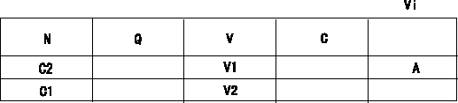
Potentiometer adjustment
Vi = applied voltage
N:Pump speed
Q:Injection quantity
V:Output voltage
C:Angle of the control lever
A:Adjusting point
B:Checking point
C1:Idle
C2:Full-speed
----------
V1=4.32+-0.03V P1=0kPa P2=0mmHg Vi=10V
----------
N1=r/min Q1=cm3/1,000st V1=V V2=V V3=V a=deg
----------
V1=4.32+-0.03V P1=0kPa P2=0mmHg Vi=10V
----------
N1=r/min Q1=cm3/1,000st V1=V V2=V V3=V a=deg
0000001901 STOP LEVER ADJUSTMENT
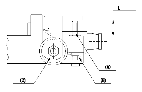
Adjustment of the stop lever
Adjust adjusting bolt (B) so that the starting injection quantity is within the standard.
Fix using nut.
(A) Adjusting nut
(C) Starting injection quantity adjusting lever
----------
----------
L=15.0~18.5mm
----------
----------
L=15.0~18.5mm
Information:
The information supplied in this service letter may not be valid after the termination date of this program. Do not perform the work outlined in this Service Letter after the termination date without first contacting your Caterpillar product analyst.
If the work described in this Program was performed on the Affected Product under PI7298, Service Letter dated October 30, 1992, DO NOT repeat the work.
This Revised Service Letter replaces the April 28, 1993 Service Letter revised March 1994. Changes have been made to the TERMINATION DATE and Affected Product.
Termination Date
August 31, 1994Problem
The fuel injection pumps used on certain Remanufactured 1160 and 3208 Engines need to be inspected for gummy deposits.
Affected Product
Model & Identification Number
1160 (57V1-34485)
3208 (9WC1-1093)
3208 (5CD1-9736, 62W1-76455 , 93Z1-10198 )
Parts Stock Remanufactured Fuel Pump Part Numbers
This program applies only to pumps in parts stock with a date code prior to November, 1993 (UUDE). Date codes are in the MM/YY mode with the standard notation of NUMERALKOD.
Parts Needed
Not applicable.
Action Required
Before installing or delivering any of the Affected Product, perform the following steps to ensure the internal fuel injection pump components are not stuck due to fuel pump gumming:
1. Remove the top cover of the fuel injection pump and check to ensure that all sleeves and levers are free and there are no gummy deposits on any of these components.2. If inspection performed in Step 1 indicates everything is clean, install top cover and return to parts stock.3. If inspection reveals components have gummy deposits, remove 12 ounces of fuel from the fuel pump housing and replace it with:- Fuel Injector Cleaneror- Carburetor/Choke Cleaner4. Allow the components to soak in cleaning solution for 45 minutes. Then, rotate the engine crankshaft to rotate the fuel injection pump and check for free movement of the lever and sleeve (on pumps only, rotate the fuel pump camshaft). This will ensure the components have the gummy deposits removed.5. If the above procedures do not free the pump assembly, remove the individual pumps from the pump housing, clean them with cleaning solution, and install them back into the housing.6. If the engine or fuel pump will be used immediately, install the cover on the fuel injection pump, and install or deliver the engine or pump.7. If the engine or fuel pump will be returned to stock, DO NOT leave the fuel injection pump full of cleaning solution because it may not contain any rust inhibitors. Remove the cleaning solution, fill the fuel injector pump with clean diesel fuel, and install the cover on the pump.Service Claim Allowances
The inspection of the pump is a .5-hour job. If the pump needs to be cleaned, an additional .5 hour may be claimed. If the individual pumps need to be removed from the pump housing for cleaning, up to an additional 1.5 hours may be claimed.
US and Canadian Dealers Only - When submitting a Parts Stock claim use 99Z00007 in the Product Identification Number Field.
Parts Disposition
Handle the parts in accordance with your Warranty Bulletin on warranty parts handling.
Have questions with 104741-4830?
Group cross 104741-4830 ZEXEL
Nissan-Diesel
104741-4830
9 460 614 115
1670084K20
INJECTION-PUMP ASSEMBLY
QD32
QD32