Information injection-pump assembly
ZEXEL
104741-4670
1047414670
Rating:
Cross reference number
ZEXEL
104741-4670
1047414670
Zexel num
Bosch num
Firm num
Name
104741-4670
INJECTION-PUMP ASSEMBLY
Calibration Data:
Adjustment conditions
Test oil
1404 Test oil ISO4113orSAEJ967d
1404 Test oil ISO4113orSAEJ967d
Test oil temperature
degC
45
45
50
Nozzle
105780-0060
Bosch type code
NP-DN0SD1510
Nozzle holder
105780-2150
Opening pressure
MPa
13
13
13.3
Opening pressure
kgf/cm2
133
133
136
Injection pipe
157805-7320
Injection pipe
Inside diameter - outside diameter - length (mm) mm 2-6-450
Inside diameter - outside diameter - length (mm) mm 2-6-450
Joint assembly
157641-4720
Tube assembly
157641-4020
Transfer pump pressure
kPa
20
20
20
Transfer pump pressure
kgf/cm2
0.2
0.2
0.2
Direction of rotation (viewed from drive side)
Right R
Right R
Injection timing adjustment
Pump speed
r/min
1000
1000
1000
Average injection quantity
mm3/st.
54.3
53.8
54.8
Difference in delivery
mm3/st.
4.5
Basic
*
Oil temperature
degC
50
48
52
Injection timing adjustment_02
Pump speed
r/min
500
500
500
Average injection quantity
mm3/st.
50.2
46.7
53.7
Oil temperature
degC
48
46
50
Injection timing adjustment_03
Pump speed
r/min
800
800
800
Average injection quantity
mm3/st.
51.8
48.3
55.3
Oil temperature
degC
50
48
52
Injection timing adjustment_04
Pump speed
r/min
1000
1000
1000
Average injection quantity
mm3/st.
54.3
53.3
55.3
Difference in delivery
mm3/st.
5
Basic
*
Oil temperature
degC
50
48
52
Injection timing adjustment_05
Pump speed
r/min
1500
1500
1500
Average injection quantity
mm3/st.
54
50.5
57.5
Oil temperature
degC
50
48
52
Injection timing adjustment_06
Pump speed
r/min
1800
1800
1800
Average injection quantity
mm3/st.
54.3
50.8
57.8
Oil temperature
degC
50
48
52
Injection quantity adjustment
Pump speed
r/min
2350
2350
2350
Average injection quantity
mm3/st.
19.2
17.2
21.2
Basic
*
Oil temperature
degC
52
50
54
Injection quantity adjustment_02
Pump speed
r/min
2600
2600
2600
Average injection quantity
mm3/st.
5
Oil temperature
degC
55
52
58
Injection quantity adjustment_03
Pump speed
r/min
2350
2350
2350
Average injection quantity
mm3/st.
19.2
16.7
21.7
Basic
*
Oil temperature
degC
52
50
54
Governor adjustment
Pump speed
r/min
350
350
350
Average injection quantity
mm3/st.
10.9
8.9
12.9
Difference in delivery
mm3/st.
2
Basic
*
Oil temperature
degC
48
46
50
Governor adjustment_02
Pump speed
r/min
350
350
350
Average injection quantity
mm3/st.
10.9
8.4
13.4
Difference in delivery
mm3/st.
2.5
Basic
*
Oil temperature
degC
48
46
50
Timer adjustment
Pump speed
r/min
100
100
100
Average injection quantity
mm3/st.
80
75
85
Basic
*
Oil temperature
degC
48
46
50
Remarks
Full
Full
Timer adjustment_02
Pump speed
r/min
100
100
100
Average injection quantity
mm3/st.
80
75
85
Oil temperature
degC
48
46
50
Remarks
Full
Full
Speed control lever angle
Pump speed
r/min
350
350
350
Average injection quantity
mm3/st.
0
0
0
Oil temperature
degC
48
46
50
Remarks
Magnet OFF at idling position
Magnet OFF at idling position
0000000901
Pump speed
r/min
1000
1000
1000
Overflow quantity with S/T ON
cm3/min
460
330
590
Oil temperature
degC
50
48
52
Stop lever angle
Pump speed
r/min
1000
1000
1000
Pressure with S/T OFF
kPa
539
519
559
Pressure with S/T OFF
kgf/cm2
5.5
5.3
5.7
Basic
*
Oil temperature
degC
50
48
52
Stop lever angle_02
Pump speed
r/min
1000
1000
1000
Pressure with S/T OFF
kPa
539
500
578
Pressure with S/T OFF
kgf/cm2
5.5
5.1
5.9
Basic
*
Oil temperature
degC
50
48
52
Stop lever angle_03
Pump speed
r/min
1800
1800
1800
Pressure with S/T OFF
kPa
736
677
795
Pressure with S/T OFF
kgf/cm2
7.5
6.9
8.1
Oil temperature
degC
50
48
52
0000001101
Pump speed
r/min
1000
1000
1000
Timer stroke with S/T OFF
mm
3.9
3.7
4.1
Basic
*
Oil temperature
degC
50
48
52
_02
Pump speed
r/min
600
600
600
Timer stroke with S/T OFF
mm
1.3
0.7
1.9
Oil temperature
degC
50
48
52
_03
Pump speed
r/min
1000
1000
1000
Timer stroke with S/T ON
mm
5.2
4.7
5.7
Timer stroke with S/T OFF
mm
3.9
3.6
4.2
Basic
*
Oil temperature
degC
50
48
52
_04
Pump speed
r/min
1800
1800
1800
Timer stroke with S/T OFF
mm
8.2
7.7
8.7
Oil temperature
degC
50
48
52
_05
Pump speed
r/min
2050
2050
2050
Timer stroke with S/T OFF
mm
8.2
7.7
8.6
Oil temperature
degC
52
50
54
0000001201
Max. applied voltage
V
8
8
8
Test voltage
V
13
12
14
0000001401
Pump speed
r/min
1000
1000
1000
Average injection quantity
mm3/st.
35
34.5
35.5
Timer stroke TA
mm
2.9
2.7
3.1
Timer stroke variation dT
mm
1
1
1
Basic
*
Oil temperature
degC
50
48
52
Remarks
OFF
OFF
_02
Pump speed
r/min
1000
1000
1000
Average injection quantity
mm3/st.
35
34
36
Timer stroke TA
mm
2.9
2.6
3.2
Timer stroke variation dT
mm
1
1
1
Basic
*
Oil temperature
degC
50
48
52
_03
Pump speed
r/min
1000
1000
1000
Average injection quantity
mm3/st.
20
17.5
22.5
Timer stroke TA
mm
1.7
1.2
2.2
Timer stroke variation dT
mm
2.2
2.2
2.2
Oil temperature
degC
50
48
52
Timing setting
K dimension
mm
3.3
3.2
3.4
KF dimension
mm
5.62
5.52
5.72
MS dimension
mm
0.9
0.8
1
Pre-stroke
mm
0.1
0.08
0.12
Control lever angle alpha
deg.
55.5
51.5
59.5
Control lever angle beta
deg.
36
31
41
Test data Ex:
0000001801 STOP LEVER ADJUSTMENT
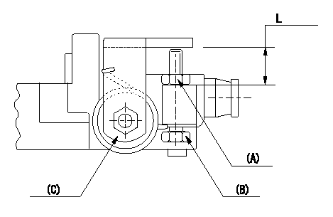
Adjustment of the stop lever
Adjust adjusting bolt (B) so that the starting injection quantity is within the standard.
Fix using nut.
(A) Adjusting nut
(C) Starting injection quantity adjusting lever
----------
----------
L=15.0~18.5mm
----------
----------
L=15.0~18.5mm
0000001901
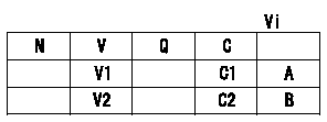
A:Adjusting point
B:Confirmation point
C:Position of the control lever
Vi:Applied voltage
V:Potentiometer output voltage
Q:Injection quantity
C1:Idle
C2:Full speed
----------
----------
V1=1.4+-0.03V V2=Above9.5V Vi=10V
----------
----------
V1=1.4+-0.03V V2=Above9.5V Vi=10V
Information:
Disassembly and Reassembly of General Parts
Oil seals
When installing oil seals, observe the following.Installation of Oil Seals to Housings
(a) Check the seal lip for scratches and damage, and be sure to position the lip correctly.(b) Apply a small amount of grease to the periphery (housing contact surface) of the oil seal before installation.(c) Use an oil seal driver that guides the seal lip and presses the seal periphery, as shown in the diagram on the right. Striking the oil seal directly with a hammer causes seal damage and results in oil leaks.
Oil seal driverInstallation of Oil Seals to Shafts
(a) Apply grease to the oil seal lip.(b) Use an oil seal guide similar to the one shown in the diagram when installing an oil seal over the stepped portion, splines, threads or key grooves.
Oil seal guideO-rings
Use an O-ring guide similar to the one shown in the diagram when installing an O-ring over the stepped portion, splines, threads or key grooves. Be sure to apply a small amount of grease to the O-ring before installation.
O-ring guideBearings
(1) When installing a bearing, be sure to push the inner or outer race that fits into the installation position. (When the inner race fits into the installation position, push the inner race into position. When the outer race fits into the installation position, push the outer race into position.) Be sure to use a bearing driver similar to the one shown in the diagram.
Bearing driver(2) Use of a press minimizes the impact on the bearing and ensures proper installation.
Using press for bearing installationLock Plates
Be sure to bend lock plates. The diagram on the right shows the methods of bending representative lock plates.
Bending lock plateSplit Pins and Spring Pins
Generally, new split pins should be installed whenever split pins are removed. Be sure to bend split pins. Be sure to check spring pins for secure installation.
Have questions with 104741-4670?
Group cross 104741-4670 ZEXEL
Nissan-Diesel
Nissan
Nissan-Diesel
Nissan-Diesel
Nissan
Nissan-Diesel
104741-4670
INJECTION-PUMP ASSEMBLY