Information injection-pump assembly
BOSCH
9 460 614 430
9460614430
ZEXEL
104741-4471
1047414471
NISSAN
1670058N13
1670058n13
Rating:
Cross reference number
BOSCH
9 460 614 430
9460614430
ZEXEL
104741-4471
1047414471
NISSAN
1670058N13
1670058n13
Zexel num
Bosch num
Firm num
Name
Calibration Data:
Adjustment conditions
Test oil
1404 Test oil ISO4113orSAEJ967d
1404 Test oil ISO4113orSAEJ967d
Test oil temperature
degC
45
45
50
Nozzle
105780-0060
Bosch type code
NP-DN0SD1510
Nozzle holder
105780-2150
Opening pressure
MPa
13
13
13.3
Opening pressure
kgf/cm2
133
133
136
Injection pipe
157805-7320
Injection pipe
Inside diameter - outside diameter - length (mm) mm 2-6-450
Inside diameter - outside diameter - length (mm) mm 2-6-450
Joint assembly
157641-4720
Tube assembly
157641-4020
Transfer pump pressure
kPa
20
20
20
Transfer pump pressure
kgf/cm2
0.2
0.2
0.2
Direction of rotation (viewed from drive side)
Right R
Right R
Injection timing adjustment
Pump speed
r/min
1000
1000
1000
Average injection quantity
mm3/st.
56.4
55.9
56.9
Difference in delivery
mm3/st.
4.5
Basic
*
Oil temperature
degC
50
48
52
Injection timing adjustment_02
Pump speed
r/min
500
500
500
Average injection quantity
mm3/st.
49.8
46.3
53.3
Oil temperature
degC
48
46
50
Injection timing adjustment_03
Pump speed
r/min
800
800
800
Average injection quantity
mm3/st.
52.9
49.4
56.4
Oil temperature
degC
50
48
52
Injection timing adjustment_04
Pump speed
r/min
1000
1000
1000
Average injection quantity
mm3/st.
56.4
55.4
57.4
Difference in delivery
mm3/st.
5
Basic
*
Oil temperature
degC
50
48
52
Injection timing adjustment_05
Pump speed
r/min
1500
1500
1500
Average injection quantity
mm3/st.
54.6
51.6
57.6
Oil temperature
degC
50
48
52
Injection timing adjustment_06
Pump speed
r/min
1800
1800
1800
Average injection quantity
mm3/st.
54.8
51.8
57.8
Oil temperature
degC
50
48
52
Injection quantity adjustment
Pump speed
r/min
2350
2350
2350
Average injection quantity
mm3/st.
20.1
18.1
22.1
Basic
*
Oil temperature
degC
52
50
54
Injection quantity adjustment_02
Pump speed
r/min
2350
2350
2350
Average injection quantity
mm3/st.
20.1
17.6
22.6
Basic
*
Oil temperature
degC
52
50
54
Injection quantity adjustment_03
Pump speed
r/min
2500
2500
2500
Average injection quantity
mm3/st.
5
Oil temperature
degC
55
52
58
Governor adjustment
Pump speed
r/min
350
350
350
Average injection quantity
mm3/st.
7.9
5.9
9.9
Difference in delivery
mm3/st.
2
Basic
*
Oil temperature
degC
48
46
50
Governor adjustment_02
Pump speed
r/min
350
350
350
Average injection quantity
mm3/st.
7.9
5.4
10.4
Difference in delivery
mm3/st.
2.5
Basic
*
Oil temperature
degC
48
46
50
Timer adjustment
Pump speed
r/min
100
100
100
Average injection quantity
mm3/st.
90
75
110
Basic
*
Oil temperature
degC
48
46
50
Timer adjustment_02
Pump speed
r/min
100
100
100
Average injection quantity
mm3/st.
90
75
110
Oil temperature
degC
48
46
50
Speed control lever angle
Pump speed
r/min
350
350
350
Average injection quantity
mm3/st.
0
0
0
Oil temperature
degC
48
46
50
Remarks
Magnet OFF at idling position
Magnet OFF at idling position
Speed control lever angle_02
Pump speed
r/min
250
250
250
Average injection quantity
mm3/st.
5
Oil temperature
degC
48
46
50
Remarks
Magnet OFF at full-load position
Magnet OFF at full-load position
0000000901
Pump speed
r/min
1000
1000
1000
Overflow quantity with S/T ON
cm3/min
500
370
630
Oil temperature
degC
50
48
52
Remarks
Without an O-ring
Without an O-ring
Stop lever angle
Pump speed
r/min
1000
1000
1000
Pressure with S/T ON
kPa
618
579
657
Pressure with S/T ON
kgf/cm2
6.3
5.9
6.7
Pressure with S/T OFF
kPa
539
519
559
Pressure with S/T OFF
kgf/cm2
5.5
5.3
5.7
Basic
*
Oil temperature
degC
50
48
52
Stop lever angle_02
Pump speed
r/min
1000
1000
1000
Pressure with S/T OFF
kPa
539
500
578
Pressure with S/T OFF
kgf/cm2
5.5
5.1
5.9
Basic
*
Oil temperature
degC
50
48
52
Stop lever angle_03
Pump speed
r/min
1600
1600
1600
Pressure with S/T OFF
kPa
686
647
725
Pressure with S/T OFF
kgf/cm2
7
6.6
7.4
Oil temperature
degC
50
48
52
0000001101
Pump speed
r/min
1000
1000
1000
Timer stroke with S/T ON
mm
6.3
5.9
6.7
Timer stroke with S/T OFF
mm
4.7
4.5
4.9
Basic
*
Oil temperature
degC
50
48
52
_02
Pump speed
r/min
600
600
600
Timer stroke with S/T OFF
mm
1.7
1.2
2.2
Oil temperature
degC
50
48
52
_03
Pump speed
r/min
1000
1000
1000
Timer stroke with S/T ON
mm
6.3
5.8
6.8
Timer stroke with S/T OFF
mm
4.7
4.4
5
Basic
*
Oil temperature
degC
50
48
52
_04
Pump speed
r/min
1600
1600
1600
Timer stroke with S/T OFF
mm
7.8
7.3
8.3
Oil temperature
degC
50
48
52
_05
Pump speed
r/min
1900
1900
1900
Timer stroke with S/T OFF
mm
9
8.5
9.4
Oil temperature
degC
50
48
52
0000001201
Max. applied voltage
V
8
8
8
Test voltage
V
13
12
14
0000001401
Pump speed
r/min
1000
1000
1000
Average injection quantity
mm3/st.
32
31.5
32.5
Timer stroke TA
mm
3.9
3.7
4.1
Timer stroke variation dT
mm
0.8
0.8
0.8
Basic
*
Oil temperature
degC
50
48
52
_02
Pump speed
r/min
1000
1000
1000
Average injection quantity
mm3/st.
32
31
33
Timer stroke TA
mm
3.9
3.6
4.2
Timer stroke variation dT
mm
0.8
0.8
0.8
Basic
*
Oil temperature
degC
50
48
52
_03
Pump speed
r/min
1000
1000
1000
Average injection quantity
mm3/st.
20
17.5
22.5
Timer stroke TA
mm
2.7
2.2
3.2
Timer stroke variation dT
mm
2
2
2
Oil temperature
degC
50
48
52
Timing setting
K dimension
mm
3.3
3.2
3.4
KF dimension
mm
5.62
5.52
5.72
MS dimension
mm
0.9
0.8
1
Pre-stroke
mm
0.1
0.08
0.12
Control lever angle alpha
deg.
55.5
51.5
59.5
Control lever angle beta
deg.
36
31
41
Test data Ex:
0000001801 POTENTIOMETER ADJUSTMENT
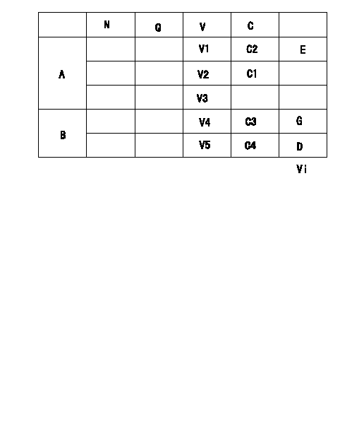
A:Potentiometer standards
B:ON, OFF switch standard
N:Pump speed
Q:Injection quantity
V:Output voltage
C:Control lever angle
C1:Full-speed
C2:Idle
E:Adjusting point
G:ON-->OFF
D:OFF-->ON
Vi:Applied voltage
----------
----------
V1=1.04+-0.03(V) V2=7.04+-1.0(V) V3=-(V) V4=1.59+-0.41(V) V5=3.89+-0.5(V) C3=9.5+-2.5(deg) C4=23.3+-3(deg) Vi=10(V)
----------
----------
V1=1.04+-0.03(V) V2=7.04+-1.0(V) V3=-(V) V4=1.59+-0.41(V) V5=3.89+-0.5(V) C3=9.5+-2.5(deg) C4=23.3+-3(deg) Vi=10(V)
0000001901 ACCELERATOR SWITCH ADJ
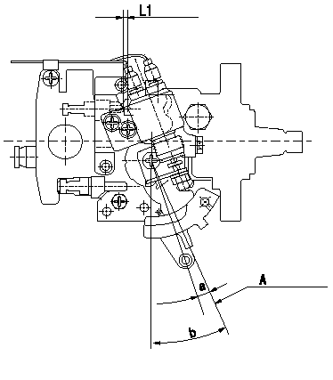
Adjustment of the accelerator switch
ON - OFF changeover point: from idle to c (shim thickness L1 mm)
Idle-d: ON
e-full: OFF
A = idle lever position
----------
c=5+2-1(deg) d=5(deg) e=5(deg) L1=3.3+-0.13(mm)
----------
a=5+2-1(deg) b=23+-2(deg) L1=(3.3(mm))
----------
c=5+2-1(deg) d=5(deg) e=5(deg) L1=3.3+-0.13(mm)
----------
a=5+2-1(deg) b=23+-2(deg) L1=(3.3(mm))
Information:
Determination Of Overhaul Timing
Generally, the engine needs an overhaul when the compression pressure of the engine becomes low, and the amounts of engine oil consumption and blow-by gas increase.Reduced power output, increased fuel consumption, low oil pressure, difficult in starting, and increased operating noise are also signs that suggest the need for an overhaul; however, since these problems can be caused by various factors, they do not serve as reliable criteria for determining the need for an overhaul.Reduced compression pressure manifests a variety of symptoms, thus making it difficult to accurately determine when the engine needs an overhaul. The following shows typical problems caused by reduced compression pressure.(1) Decreased output power(2) Increased fuel consumption(3) Increased engine oil consumption(4) Increased blow-by gas from breather due to leakage of combustion gas through worn cylinder liners and piston rings(5) Increased gas leakage due to poor seating of inlet and exhaust valves(6) Difficulty in starting(7) Increased noise from engine parts(8) Abnormal exhaust color after warm-up operationThe engine can exhibit these conditions in various combinations.Some of these problems are directly caused by worn engine parts, while others are not.Phenomena described in (2) and (6) can also result from improper injection volume, incorrect fuel injection timing, worn plungers, defective nozzles, and faulty conditions of electrical devices such as battery, starter and alternator.The most valid reason to overhaul an engine is a decrease in the compression pressure due to worn cylinder liners and pistons, as described in (4), and once this is determined, other symptoms should be taken into consideration in order to make the final judgement of whether the engine needs an overhaul.Measurement of Compression Pressure
Measurement of compression pressurePreparation For Inspection
Check the following before inspection.(1) Make sure that the engine oil, air cleaner, starter, battery, etc. are in normal operating condition.Inspection
(1) Move the control lever to the Stop position.(2) Remove the glow plugs from all cylinders, and attach the gage adapter and compression gage to the cylinder to be tested.(3) Crank the engine with the starter, and read the compression gage indication when the indication stabilizes.(4) If the measured compression pressure is lower than the limit, consider overhauling the engine.
(a) Measure the compression pressure in all cylinders.(b) As compression pressure varies with the engine speed, measure the engine speed at the same time.
Measure the compression pressure while the engine is running at 150 to 200 min-1. The oil and coolant temperatures should be between 20 and 30 °C [68 and 86°F].
It is important to regularly check the compression pressure so that you can tell the difference. * New or overhauled engines have slightly higher compression pressure.* The compression pressure settles to the standard value as the piston rings and valve seats fit in.* As wear progresses further, the compression pressure drops.