Information injection-pump assembly
BOSCH
9 460 614 429
9460614429
ZEXEL
104741-4461
1047414461
NISSAN
1670058N12
1670058n12
Rating:
Cross reference number
BOSCH
9 460 614 429
9460614429
ZEXEL
104741-4461
1047414461
NISSAN
1670058N12
1670058n12
Zexel num
Bosch num
Firm num
Name
Calibration Data:
Adjustment conditions
Test oil
1404 Test oil ISO4113orSAEJ967d
1404 Test oil ISO4113orSAEJ967d
Test oil temperature
degC
45
45
50
Nozzle
105780-0060
Bosch type code
NP-DN0SD1510
Nozzle holder
105780-2150
Opening pressure
MPa
13
13
13.3
Opening pressure
kgf/cm2
133
133
136
Injection pipe
157805-7320
Injection pipe
Inside diameter - outside diameter - length (mm) mm 2-6-450
Inside diameter - outside diameter - length (mm) mm 2-6-450
Joint assembly
157641-4720
Tube assembly
157641-4020
Transfer pump pressure
kPa
20
20
20
Transfer pump pressure
kgf/cm2
0.2
0.2
0.2
Direction of rotation (viewed from drive side)
Right R
Right R
Injection timing adjustment
Pump speed
r/min
1000
1000
1000
Average injection quantity
mm3/st.
56.4
55.9
56.9
Difference in delivery
mm3/st.
4.5
Basic
*
Oil temperature
degC
50
48
52
Injection timing adjustment_02
Pump speed
r/min
500
500
500
Average injection quantity
mm3/st.
49.8
46.3
53.3
Oil temperature
degC
48
46
50
Injection timing adjustment_03
Pump speed
r/min
800
800
800
Average injection quantity
mm3/st.
52.9
49.4
56.4
Oil temperature
degC
50
48
52
Injection timing adjustment_04
Pump speed
r/min
1000
1000
1000
Average injection quantity
mm3/st.
56.4
55.4
57.4
Difference in delivery
mm3/st.
5
Basic
*
Oil temperature
degC
50
48
52
Injection timing adjustment_05
Pump speed
r/min
1500
1500
1500
Average injection quantity
mm3/st.
54.6
51.6
57.6
Oil temperature
degC
50
48
52
Injection timing adjustment_06
Pump speed
r/min
1800
1800
1800
Average injection quantity
mm3/st.
54.8
51.8
57.8
Oil temperature
degC
50
48
52
Injection quantity adjustment
Pump speed
r/min
2350
2350
2350
Average injection quantity
mm3/st.
20.1
18.1
22.1
Basic
*
Oil temperature
degC
52
50
54
Injection quantity adjustment_02
Pump speed
r/min
2350
2350
2350
Average injection quantity
mm3/st.
20.1
17.6
22.6
Basic
*
Oil temperature
degC
52
50
54
Injection quantity adjustment_03
Pump speed
r/min
2500
2500
2500
Average injection quantity
mm3/st.
5
Oil temperature
degC
55
52
58
Governor adjustment
Pump speed
r/min
350
350
350
Average injection quantity
mm3/st.
7.9
5.9
9.9
Difference in delivery
mm3/st.
2
Basic
*
Oil temperature
degC
48
46
50
Governor adjustment_02
Pump speed
r/min
350
350
350
Average injection quantity
mm3/st.
7.9
5.4
10.4
Difference in delivery
mm3/st.
2.5
Basic
*
Oil temperature
degC
48
46
50
Timer adjustment
Pump speed
r/min
100
100
100
Average injection quantity
mm3/st.
90
75
110
Basic
*
Oil temperature
degC
48
46
50
Timer adjustment_02
Pump speed
r/min
100
100
100
Average injection quantity
mm3/st.
90
75
110
Oil temperature
degC
48
46
50
Speed control lever angle
Pump speed
r/min
350
350
350
Average injection quantity
mm3/st.
0
0
0
Oil temperature
degC
48
46
50
Remarks
Magnet OFF at idling position
Magnet OFF at idling position
Speed control lever angle_02
Pump speed
r/min
250
250
250
Average injection quantity
mm3/st.
5
Oil temperature
degC
48
46
50
Remarks
Magnet OFF at full-load position
Magnet OFF at full-load position
0000000901
Pump speed
r/min
1000
1000
1000
Oil temperature
degC
50
48
52
Remarks
MEASURE
MEASURE
Stop lever angle
Pump speed
r/min
1000
1000
1000
Pressure
kPa
539
519
559
Pressure
kgf/cm2
5.5
5.3
5.7
Basic
*
Oil temperature
degC
50
48
52
Stop lever angle_02
Pump speed
r/min
1000
1000
1000
Pressure
kPa
539
500
578
Pressure
kgf/cm2
5.5
5.1
5.9
Basic
*
Oil temperature
degC
50
48
52
Stop lever angle_03
Pump speed
r/min
1600
1600
1600
Pressure
kPa
686
647
725
Pressure
kgf/cm2
7
6.6
7.4
Oil temperature
degC
50
48
52
0000001101
Pump speed
r/min
1000
1000
1000
Timer stroke
mm
4.7
4.5
4.9
Basic
*
Oil temperature
degC
50
48
52
_02
Pump speed
r/min
600
600
600
Timer stroke
mm
2.4
1.9
2.9
Oil temperature
degC
50
48
52
_03
Pump speed
r/min
1000
1000
1000
Timer stroke
mm
4.7
4.4
5
Basic
*
Oil temperature
degC
50
48
52
_04
Pump speed
r/min
1600
1600
1600
Timer stroke
mm
7.8
7.3
8.3
Oil temperature
degC
50
48
52
_05
Pump speed
r/min
1900
1900
1900
Timer stroke
mm
9
8.5
9.4
Oil temperature
degC
50
48
52
0000001201
Max. applied voltage
V
8
8
8
Test voltage
V
13
12
14
0000001401
Pump speed
r/min
1000
1000
1000
Average injection quantity
mm3/st.
32
31.5
32.5
Timer stroke TA
mm
3.9
3.7
4.1
Timer stroke variation dT
mm
0.8
0.8
0.8
Basic
*
Oil temperature
degC
50
48
52
_02
Pump speed
r/min
1000
1000
1000
Average injection quantity
mm3/st.
32
31
33
Timer stroke TA
mm
3.9
3.6
4.2
Timer stroke variation dT
mm
0.8
0.8
0.8
Basic
*
Oil temperature
degC
50
48
52
_03
Pump speed
r/min
1000
1000
1000
Average injection quantity
mm3/st.
20
17.5
22.5
Timer stroke TA
mm
2.7
2.2
3.2
Timer stroke variation dT
mm
2
2
2
Oil temperature
degC
50
48
52
Timing setting
K dimension
mm
3.3
3.2
3.4
KF dimension
mm
5.62
5.52
5.72
MS dimension
mm
0.9
0.8
1
Pre-stroke
mm
0.1
0.08
0.12
Control lever angle alpha
deg.
55.5
53.5
57.5
Control lever angle beta
deg.
36
31
41
Test data Ex:
0000001801 POTENTIOMETER ADJUSTMENT
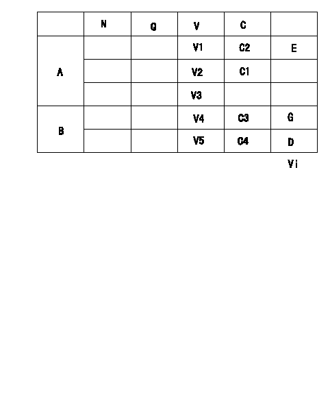
A:Potentiometer standards
B:ON, OFF switch standard
N:Pump speed
Q:Injection quantity
V:Output voltage
C:Control lever angle
C1:Full-speed
C2:Idle
E:Adjusting point
G:ON-->OFF
D:OFF-->ON
Vi:Applied voltage
*The switch voltage specification is the value when the idle lever position is 0 volts.
----------
----------
V1=1.04+-0.03(V) V2=7.04+-1.0(V) V3=-(V) V4=1.59+-0.41(V) V5=3.89+-0.5(V) C3=9.5+-2.5(deg) C4=23.3+-3(deg) Vi=10(V)
----------
----------
V1=1.04+-0.03(V) V2=7.04+-1.0(V) V3=-(V) V4=1.59+-0.41(V) V5=3.89+-0.5(V) C3=9.5+-2.5(deg) C4=23.3+-3(deg) Vi=10(V)
Information:
ACTION REQUIRED
Flash engine ECM with new 422-8397 Software on machines located in North America.
Flash engine ECM with new 422-8398 Software on machines located in Europe.
Refer to Special Instruction, REHS7927 for instructions on replacing the diesel particulate filter pressure lines group.
Refer to Special Instruction, REHS7197 for instructions on installing the engine cooling fan bypass feature.
SERVICE CLAIM ALLOWANCES
Product smu/age whichever comes first Caterpillar Dealer Suggested Customer Suggested
Parts % Labor Hrs% Parts % Labor Hrs% Parts % Labor Hrs%
*******Group 1*******
0-5000 hrs,
0-36 mo 100.0% 100.0% 0.0% 0.0% 0.0% 0.0%
This is a 12.0-hour job for Group 1
Travel and mileage will be allowed under this program
Product smu/age whichever comes first Caterpillar Dealer Suggested Customer Suggested
Parts % Labor Hrs% Parts % Labor Hrs% Parts % Labor Hrs%
*******Group 2*******
0-5000 hrs,
0-36 mo 100.0% 100.0% 0.0% 0.0% 0.0% 0.0%
This is a 12.0-hour job for Group 2
Travel and mileage will be allowed under this program
PARTS DISPOSITION
Handle the parts in accordance with your Warranty Bulletin on warranty parts handling.