Information injection-pump assembly
ZEXEL
104741-4240
1047414240
NISSAN-DIESEL
1670045K00
1670045k00

Rating:
Cross reference number
ZEXEL
104741-4240
1047414240
NISSAN-DIESEL
1670045K00
1670045k00
Zexel num
Bosch num
Firm num
Name
Calibration Data:
Adjustment conditions
Test oil
1404 Test oil ISO4113orSAEJ967d
1404 Test oil ISO4113orSAEJ967d
Test oil temperature
degC
45
45
50
Nozzle
105780-0060
Bosch type code
NP-DN0SD1510
Nozzle holder
105780-2150
Opening pressure
MPa
13
13
13.3
Opening pressure
kgf/cm2
133
133
136
Injection pipe
157805-7320
Injection pipe
Inside diameter - outside diameter - length (mm) mm 2-6-450
Inside diameter - outside diameter - length (mm) mm 2-6-450
Joint assembly
157641-4720
Tube assembly
157641-4020
Transfer pump pressure
kPa
20
20
20
Transfer pump pressure
kgf/cm2
0.2
0.2
0.2
Direction of rotation (viewed from drive side)
Right R
Right R
Injection timing adjustment
Pump speed
r/min
800
800
800
Average injection quantity
mm3/st.
54.7
54.2
55.2
Difference in delivery
mm3/st.
4
Basic
*
Oil temperature
degC
50
48
52
Injection timing adjustment_02
Pump speed
r/min
300
300
300
Average injection quantity
mm3/st.
40.2
40.2
40.2
Oil temperature
degC
48
46
50
Injection timing adjustment_03
Pump speed
r/min
500
500
500
Average injection quantity
mm3/st.
41.6
38.1
45.1
Oil temperature
degC
48
46
50
Injection timing adjustment_04
Pump speed
r/min
700
700
700
Average injection quantity
mm3/st.
50.3
50.3
50.3
Oil temperature
degC
50
48
52
Injection timing adjustment_05
Pump speed
r/min
800
800
800
Average injection quantity
mm3/st.
54.7
53.7
55.7
Difference in delivery
mm3/st.
4.5
Basic
*
Oil temperature
degC
50
48
52
Injection timing adjustment_06
Pump speed
r/min
1200
1200
1200
Average injection quantity
mm3/st.
60.3
58.3
62.3
Oil temperature
degC
50
48
52
Injection quantity adjustment
Pump speed
r/min
1350
1350
1350
Average injection quantity
mm3/st.
14.1
11.1
17.1
Basic
*
Oil temperature
degC
50
48
52
Injection quantity adjustment_02
Pump speed
r/min
1350
1350
1350
Average injection quantity
mm3/st.
14.1
10.6
17.6
Basic
*
Oil temperature
degC
50
48
52
Injection quantity adjustment_03
Pump speed
r/min
1500
1500
1500
Average injection quantity
mm3/st.
5
Oil temperature
degC
50
48
52
Governor adjustment
Pump speed
r/min
350
350
350
Average injection quantity
mm3/st.
8.5
6.5
10.5
Difference in delivery
mm3/st.
2
Basic
*
Oil temperature
degC
48
46
50
Governor adjustment_02
Pump speed
r/min
250
250
250
Average injection quantity
mm3/st.
33.5
27.5
39.5
Oil temperature
degC
48
46
50
Governor adjustment_03
Pump speed
r/min
350
350
350
Average injection quantity
mm3/st.
8.5
6.5
10.5
Difference in delivery
mm3/st.
2.5
Basic
*
Oil temperature
degC
48
46
50
Timer adjustment
Pump speed
r/min
100
100
100
Average injection quantity
mm3/st.
80
75
85
Basic
*
Oil temperature
degC
48
46
50
Remarks
Full
Full
Timer adjustment_02
Pump speed
r/min
100
100
100
Average injection quantity
mm3/st.
80
75
85
Basic
*
Oil temperature
degC
48
46
50
Speed control lever angle
Pump speed
r/min
350
350
350
Average injection quantity
mm3/st.
0
0
0
Oil temperature
degC
48
46
50
Remarks
Magnet OFF at idling position
Magnet OFF at idling position
Speed control lever angle_02
Pump speed
r/min
250
250
250
Average injection quantity
mm3/st.
5
Oil temperature
degC
48
46
50
Remarks
Magnet OFF at full-load position
Magnet OFF at full-load position
0000000901
Pump speed
r/min
900
900
900
Overflow quantity
cm3/min
340
210
470
Oil temperature
degC
50
48
52
Stop lever angle
Pump speed
r/min
900
900
900
Pressure
kPa
265
236
294
Pressure
kgf/cm2
2.7
2.4
3
Basic
*
Oil temperature
degC
50
48
52
Stop lever angle_02
Pump speed
r/min
900
900
900
Pressure
kPa
265
226
304
Pressure
kgf/cm2
2.7
2.3
3.1
Basic
*
Oil temperature
degC
50
48
52
Stop lever angle_03
Pump speed
r/min
1100
1100
1100
Pressure
kPa
304
265
343
Pressure
kgf/cm2
3.1
2.7
3.5
Oil temperature
degC
50
48
52
0000001101
Pump speed
r/min
900
900
900
Timer stroke
mm
1.8
1.6
2
Basic
*
Oil temperature
degC
50
48
52
_02
Pump speed
r/min
900
900
900
Timer stroke
mm
1.8
1.4
2.2
Basic
*
Oil temperature
degC
50
48
52
_03
Pump speed
r/min
1100
1100
1100
Timer stroke
mm
3
2.4
3.6
Oil temperature
degC
50
48
52
_04
Pump speed
r/min
1350
1350
1350
Timer stroke
mm
4.1
3.6
4.5
Oil temperature
degC
50
48
52
0000001201
Max. applied voltage
V
8
8
8
Test voltage
V
13
12
14
Timing setting
K dimension
mm
2.8
2.7
2.9
KF dimension
mm
5
4.9
5.1
MS dimension
mm
1.7
1.6
1.8
Pre-stroke
mm
0.45
0.43
0.47
Control lever angle alpha
deg.
25
21
29
Control lever angle beta
deg.
37
32
42
Test data Ex:
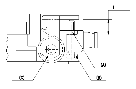
0000001801 STOP LEVER ADJUSTMENT

Adjustment of the stop lever
Adjust adjusting bolt (B) so that the starting injection quantity is within the standard.
Fix using nut.
(A) Adjusting nut
(C) Starting injection quantity adjusting lever
----------
----------
L=15.0~18.5mm
----------
----------
L=15.0~18.5mm
Information:
3-164D, 3-179D, 4-219D, 4-239D, 4-239T, 6-329D, 6-359D, Or 6-359T Engine
Removal
Fig. 1-Oil Cooler LinesDisconnect coolant lines (1, Fig. 1).Remove oil filter (2).
Fig. 2-Oil Cooler NippleUnscrew oil cooler nipple (Fig. 2) and lift oil cooler off of cylinder block.Remove four sided packing from bottom of oil cooler.Repair
Pressure check the coolant side of the oil cooler using 15 psi (103 kPa) (1 bar) maximum air pressure.Remove oil cooler bypass valve by driving it out the bottom of the oil cooler from the top side.
Fig. 3-Oil Cooler Bypass Valve and SpringInspect bypass valve and spring (Fig. 3) for damage and replace as necessary.Installation
Fig. 4-Four Sided PackingInstall new four sided packing (Fig. 4) on bottom of oil cooler.Position oil cooler on engine and install oil cooler nipple.
Fig. 5-Oil Cooler NippleOil cooler nipple torque (Fig. 5) ... 20 to 25 lb-ft(27 to 34 N m) (3.0 to 3.5 kg-m)Connect coolant hoses to oil cooler and install new oil filter (Group 0407).4-276D, 4-276T, 6-414D Or 6414T Engine
Removal
Fig. 6-Oil Cooler Assembly RemovalDisconnect coolant lines (1, Fig. 6) and remove oil filter (2).Remove oil cooler assembly attaching cap screws (3).Remove oil filter housing (4) from oil cooler.Repair
Remove top and bottom covers.
Fig. 7-Remove Oil CoolerUsing a suitable driver, drive oil cooler out of housing from bottom side (Fig. 7).
Fig. 8-Remove Oil Cooler Relief ValveDrive oil cooler bypass valve out the bottom from the top using a pin punch against the top of the valve (Fig. 8).
Fig. 9-Oil CoolerInspect oil cooler for damage or build-up of foreign material and clean as needed.The oil cooler can be pressure checked with a maximum of 50 psi (345 kPa) (3 bar) air pressure.
Fig. 10-Oil Cooler Bypass Valve Spring LengthCheck oil cooler bypass valve spring length:Valve spring length (Fig. 10) ... 1.91 inch(48.5 mm)when compressed with ... 29.5 to 37.5 lb(131 to 167 N)
Fig. 11-Remove O-RingsRemove O-rings from housing at bottom of oil cooler bore.Remove all gasket residue from parts.Installation
Fig. 12-Install Oil Cooler Relief ValvePosition oil cooler relief valve spring (1, Fig. 12), valve (2), and valve seat (3) in bore in bottom of housing (4).
Fig. 13-Drive Oil Cooler Relief Valve SeatUsing a suitable driver (Fig. 13), drive the valve seat into the housing until the seat bottoms.
Fig. 14-O-Ring InstallationInstall new O-rings in housing at bottom of oil cooler bore, black O-ring in upper groove (A, Fig. 14) and red O-ring in lower groove (B).Using new gasket, install oil cooler in housing from top side, being careful not to shear O-rings.Using new gaskets, install top and bottom covers and oil filter housing.Position oil cooler assembly on engine and install cap screws.Connect oil cooler coolant lines and install a new oil filter.
Removal
Fig. 1-Oil Cooler LinesDisconnect coolant lines (1, Fig. 1).Remove oil filter (2).
Fig. 2-Oil Cooler NippleUnscrew oil cooler nipple (Fig. 2) and lift oil cooler off of cylinder block.Remove four sided packing from bottom of oil cooler.Repair
Pressure check the coolant side of the oil cooler using 15 psi (103 kPa) (1 bar) maximum air pressure.Remove oil cooler bypass valve by driving it out the bottom of the oil cooler from the top side.
Fig. 3-Oil Cooler Bypass Valve and SpringInspect bypass valve and spring (Fig. 3) for damage and replace as necessary.Installation
Fig. 4-Four Sided PackingInstall new four sided packing (Fig. 4) on bottom of oil cooler.Position oil cooler on engine and install oil cooler nipple.
Fig. 5-Oil Cooler NippleOil cooler nipple torque (Fig. 5) ... 20 to 25 lb-ft(27 to 34 N m) (3.0 to 3.5 kg-m)Connect coolant hoses to oil cooler and install new oil filter (Group 0407).4-276D, 4-276T, 6-414D Or 6414T Engine
Removal
Fig. 6-Oil Cooler Assembly RemovalDisconnect coolant lines (1, Fig. 6) and remove oil filter (2).Remove oil cooler assembly attaching cap screws (3).Remove oil filter housing (4) from oil cooler.Repair
Remove top and bottom covers.
Fig. 7-Remove Oil CoolerUsing a suitable driver, drive oil cooler out of housing from bottom side (Fig. 7).
Fig. 8-Remove Oil Cooler Relief ValveDrive oil cooler bypass valve out the bottom from the top using a pin punch against the top of the valve (Fig. 8).
Fig. 9-Oil CoolerInspect oil cooler for damage or build-up of foreign material and clean as needed.The oil cooler can be pressure checked with a maximum of 50 psi (345 kPa) (3 bar) air pressure.
Fig. 10-Oil Cooler Bypass Valve Spring LengthCheck oil cooler bypass valve spring length:Valve spring length (Fig. 10) ... 1.91 inch(48.5 mm)when compressed with ... 29.5 to 37.5 lb(131 to 167 N)
Fig. 11-Remove O-RingsRemove O-rings from housing at bottom of oil cooler bore.Remove all gasket residue from parts.Installation
Fig. 12-Install Oil Cooler Relief ValvePosition oil cooler relief valve spring (1, Fig. 12), valve (2), and valve seat (3) in bore in bottom of housing (4).
Fig. 13-Drive Oil Cooler Relief Valve SeatUsing a suitable driver (Fig. 13), drive the valve seat into the housing until the seat bottoms.
Fig. 14-O-Ring InstallationInstall new O-rings in housing at bottom of oil cooler bore, black O-ring in upper groove (A, Fig. 14) and red O-ring in lower groove (B).Using new gasket, install oil cooler in housing from top side, being careful not to shear O-rings.Using new gaskets, install top and bottom covers and oil filter housing.Position oil cooler assembly on engine and install cap screws.Connect oil cooler coolant lines and install a new oil filter.