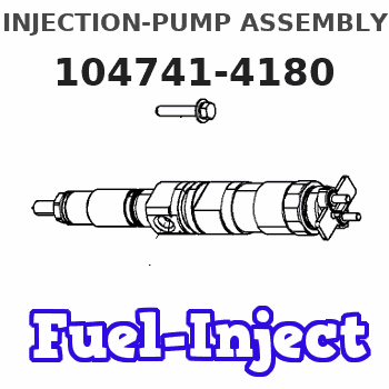
Information injection-pump assembly
BOSCH
9 460 612 969
9460612969
ZEXEL
104741-4180
1047414180
Rating:
Components :
| 0. | INJECTION-PUMP ASSEMBLY | 104741-4180 |
| 1. | _ | |
| 2. | FUEL INJECTION PUMP | 104641-4180 |
| 3. | NUMBER PLATE | 146951-3500 |
| 4. | _ | |
| 5. | CAPSULE | |
| 6. | ADJUSTING DEVICE | |
| 7. | NOZZLE AND HOLDER ASSY | 105141-1961 |
| 8. | Nozzle and Holder | 16600-T9000 |
| 9. | Open Pre:MPa(Kqf/cm2) | 9.8{100} |
| 10. | NOZZLE-HOLDER | 105071-1271 |
| 11. | NOZZLE | 105000-1080 |
Scheme ###:
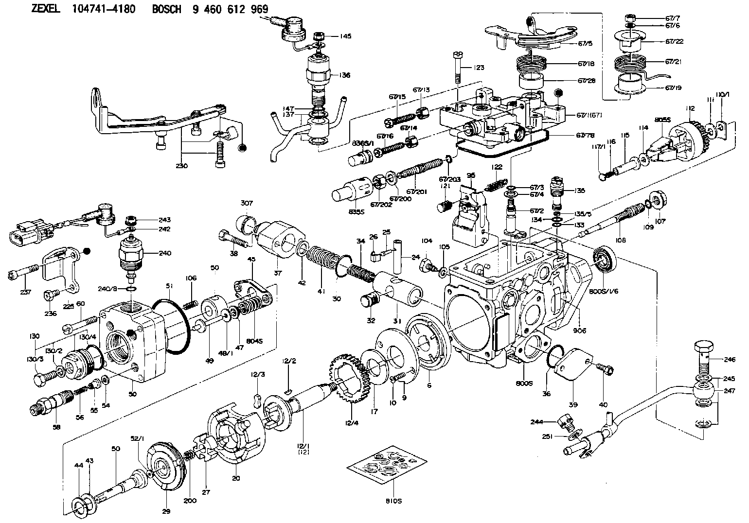
| 1/6. | [1] | 146601-0900 | PACKING RING |
| 6. | [1] | 146100-0420 | SUPPLY PUMP |
| 9. | [1] | 146103-0100 | COVER |
| 10. | [2] | 139104-0000 | FLAT-HEAD SCREW |
| 12. | [1] | 146200-0020 | DRIVE SHAFT |
| 12/1. | [1] | 146200-0000 | DRIVE SHAFT |
| 12/2. | [1] | 146201-0000 | WOODRUFF KEY |
| 12/3. | [2] | 146202-0100 | DAMPER |
| 12/4. | [1] | 146203-0000 | TOOTHED GEAR |
| 17. | [1] | 146204-0000 | PLAIN WASHER |
| 20. | [1] | 146210-2320 | ROLLER SET |
| 24. | [1] | 146303-0000 | BEARING PIN |
| 25. | [1] | 146304-0000 | BEARING PIN |
| 26. | [1] | 146305-0000 | CLAMPING BAND |
| 27. | [1] | 146205-0000 | SLOTTED WASHER |
| 29. | [1] | 146220-2120 | CAM PLATE |
| 30. | [1] | 146600-0800 | O-RING |
| 31. | [1] | 146311-5620 | PUMP PLUNGER |
| 32. | [1] | 146301-0000 | SLIDING PIECE |
| 34. | [1] | 146312-2500 | COMPRESSION SPRING |
| 34B. | [1] | 146312-2400 | COMPRESSION SPRING |
| 34C. | [1] | 146312-2300 | COMPRESSION SPRING |
| 36. | [1] | 146600-0800 | O-RING |
| 37. | [1] | 146310-3920 | COVER |
| 38. | [2] | 146620-6300 | BLEEDER SCREW |
| 39. | [1] | 146310-0100 | COVER |
| 40. | [2] | 146620-5000 | BLEEDER SCREW |
| 41. | [1] | 146312-1900 | COMPRESSION SPRING |
| 42. | [1] | 146602-8500 | PLAIN WASHER |
| 43. | [1] | 146230-0000 | SHIM |
| 44. | [1] | 146230-0100 | PLAIN WASHER |
| 45. | [1] | 146231-0001 | SLOTTED WASHER |
| 47. | [2] | 146233-0000 | SLOTTED WASHER |
| 48/1. | [1] | 146603-0000 | SHIM D17.0&5.2T0.50 |
| 48/1. | [1] | 146603-0100 | SHIM D17.0&5.2T0.80 |
| 48/1. | [1] | 146603-0200 | SHIM D17.0&5.2T1.00 |
| 48/1. | [1] | 146603-0300 | SHIM D17.0&5.2T1.20 |
| 48/1. | [1] | 146603-0400 | SHIM D17.0&5.2T1.50 |
| 48/1. | [1] | 146603-0500 | SHIM D17.0&5.2T1.80 |
| 48/1. | [1] | 146603-0600 | SHIM D17.0&5.2T2.00 |
| 48/1. | [1] | 146690-1400 | SHIM D17&5.2T0.9 |
| 48/1. | [1] | 146690-1500 | SHIM D17&5.2T1.1 |
| 48/1. | [1] | 146690-1600 | SHIM D17&5.2T1.3 |
| 48/1. | [1] | 146690-1700 | SHIM D17&5.2T1.4 |
| 48/1. | [1] | 146690-1800 | SHIM D17&5.2T1.6 |
| 48/1. | [1] | 146690-1900 | SHIM D17&5.2T1.7 |
| 48/1. | [1] | 146690-5800 | SHIM |
| 48/1. | [1] | 146690-5900 | SHIM |
| 48/1. | [1] | 146690-6000 | SHIM |
| 48/1. | [1] | 146690-6100 | SHIM |
| 48/1. | [1] | 146690-6200 | SHIM |
| 48/1. | [1] | 146690-6300 | SHIM |
| 48/1. | [1] | 146690-6400 | SHIM |
| 48/1. | [1] | 146690-6500 | SHIM |
| 48/1. | [1] | 146690-6600 | SHIM |
| 48/1. | [1] | 146690-6700 | SHIM |
| 48/1. | [1] | 146690-6800 | SHIM |
| 48/1. | [1] | 146690-6900 | SHIM |
| 48/1. | [1] | 146690-7000 | SHIM |
| 48/1. | [1] | 146690-7100 | SHIM |
| 48/1. | [1] | 146690-7200 | SHIM |
| 48/1. | [1] | 146690-7300 | SHIM |
| 48/1. | [1] | 146690-7400 | SHIM |
| 48/1. | [1] | 146690-7500 | SHIM |
| 48/1. | [1] | 146690-7800 | SHIM |
| 49. | [2] | 146234-0020 | GUIDE PIN |
| 50. | [1] | 146403-3320 | HYDRAULIC HEAD |
| 50. | [1] | 146403-3320 | HYDRAULIC HEAD |
| 50. | [1] | 146403-3320 | HYDRAULIC HEAD |
| 51. | [1] | 146600-0000 | O-RING |
| 52/1. | [1] | 146420-0000 | SHIM D9.5&3.0T1.90 |
| 52/1. | [1] | 146420-0100 | SHIM D9.5&3.0T1.92 |
| 52/1. | [1] | 146420-0200 | SHIM D9.5&3.0T1.94 |
| 52/1. | [1] | 146420-0300 | SHIM D9.5&3.0T1.96 |
| 52/1. | [1] | 146420-0400 | SHIM D9.5&3.0T1.98 |
| 52/1. | [1] | 146420-0500 | SHIM D9.5&3.0T2.00 |
| 52/1. | [1] | 146420-0600 | SHIM D9.5&3.0T2.02 |
| 52/1. | [1] | 146420-0700 | SHIM D9.5&3.0T2.04 |
| 52/1. | [1] | 146420-0800 | SHIM D9.5&3.0T2.06 |
| 52/1. | [1] | 146420-0900 | SHIM D9.5&3.0T2.08 |
| 52/1. | [1] | 146420-1000 | SHIM D9.5&3.0T2.10 |
| 52/1. | [1] | 146420-1100 | SHIM D9.5&3.0T2.12 |
| 52/1. | [1] | 146420-1200 | SHIM D9.5&3.0T2.14 |
| 52/1. | [1] | 146420-1300 | SHIM D9.5&3.0T2.16 |
| 52/1. | [1] | 146420-1400 | SHIM D9.5&3.0T2.18 |
| 52/1. | [1] | 146420-1500 | SHIM D9.5&3.0T2.20 |
| 52/1. | [1] | 146420-1600 | SHIM D9.5&3.0T2.22 |
| 52/1. | [1] | 146420-1700 | SHIM D9.5&3.0T2.24 |
| 52/1. | [1] | 146420-1800 | SHIM D9.5&3.0T2.26 |
| 52/1. | [1] | 146420-1900 | SHIM D9.5&3.0T2.28 |
| 52/1. | [1] | 146420-2000 | SHIM D9.5&3.0T2.30 |
| 52/1. | [1] | 146420-2100 | SHIM D9.5&3.0T2.32 |
| 52/1. | [1] | 146420-2200 | SHIM D9.5&3.0T2.34 |
| 52/1. | [1] | 146420-2300 | SHIM D9.5&3.0T2.36 |
| 52/1. | [1] | 146420-2400 | SHIM D9.5&3.0T2.38 |
| 52/1. | [1] | 146420-2500 | SHIM D9.5&3.0T2.40 |
| 52/1. | [1] | 146420-2600 | SHIM D9.5&3.0T2.42 |
| 52/1. | [1] | 146420-2700 | SHIM D9.5&3.0T2.44 |
| 52/1. | [1] | 146420-2800 | SHIM D9.5&3.0T2.46 |
| 52/1. | [1] | 146420-2900 | SHIM D9.5&3.0T2.48 |
| 52/1. | [1] | 146420-3000 | SHIM D9.5&3.0T2.50 |
| 52/1. | [1] | 146420-3100 | SHIM D9.5&3.0T2.52 |
| 52/1. | [1] | 146420-3200 | SHIM D9.5&3.0T2.54 |
| 52/1. | [1] | 146420-3300 | SHIM D9.5&3.0T2.56 |
| 52/1. | [1] | 146420-3400 | SHIM D9.5&3.0T2.58 |
| 52/1. | [1] | 146420-3500 | SHIM D9.5&3.0T2.60 |
| 52/1. | [1] | 146420-3600 | SHIM D9.5&3.0T2.62 |
| 52/1. | [1] | 146420-3700 | SHIM D9.5&3.0T2.64 |
| 52/1. | [1] | 146420-3800 | SHIM D9.5&3.0T2.66 |
| 52/1. | [1] | 146420-3900 | SHIM D9.5&3.0T2.68 |
| 52/1. | [1] | 146420-4000 | SHIM D9.5&3.0T2.70 |
| 52/1. | [1] | 146420-4100 | SHIM D9.5&3.0T2.72 |
| 52/1. | [1] | 146420-4200 | SHIM D9.5&3.0T2.74 |
| 52/1. | [1] | 146420-4300 | SHIM D9.5&3.0T2.76 |
| 52/1. | [1] | 146420-4400 | SHIM D9.5&3.0T2.78 |
| 52/1. | [1] | 146420-4500 | SHIM D9.5&3.0T2.80 |
| 52/1. | [1] | 146420-4600 | SHIM D9.5&3.0T2.82 |
| 52/1. | [1] | 146420-4700 | SHIM D9.5&3.0T2.84 |
| 52/1. | [1] | 146420-4800 | SHIM D9.5&3.0T2.86 |
| 52/1. | [1] | 146420-4900 | SHIM D9.5&3.0T2.88 |
| 52/1. | [1] | 146420-5000 | SHIM D9.5&3.0T2.90 |
| 52/1. | [1] | 146420-5100 | SHIM D9.5&3.0T1.74 |
| 52/1. | [1] | 146420-5200 | SHIM D9.5&3.0T1.76 |
| 52/1. | [1] | 146420-5300 | SHIM D9.5&3.0T1.78 |
| 52/1. | [1] | 146420-5400 | SHIM D9.5&3.0T1.80 |
| 52/1. | [1] | 146420-5500 | SHIM D9.5&3.0T1.82 |
| 52/1. | [1] | 146420-5600 | SHIM D9.5&3.0T1.84 |
| 52/1. | [1] | 146420-5700 | SHIM D9.5&3.0T1.86 |
| 52/1. | [1] | 146420-5800 | SHIM D9.5&3.0T1.88 |
| 54. | [4] | 146433-0100 | GASKET D12&6.4T1.00 |
| 55. | [4] | 146430-0120 | DELIVERY-VALVE ASSEMBLY |
| 56. | [4] | 146432-0000 | COMPRESSION SPRING |
| 58. | [4] | 146440-0220 | FITTING |
| 60. | [3] | 139106-0100 | FLAT-HEAD SCREW |
| 67. | [1] | 146820-2620 | GOVERNOR COVER |
| 67/1. | [1] | 146805-5020 | GOVERNOR COVER |
| 67/2. | [1] | 146515-2520 | CONTROL SHAFT |
| 67/3. | [1] | 146600-0100 | O-RING |
| 67/4. | [1] | 139310-0200 | PLAIN WASHER |
| 67/5. | [1] | 146535-5110 | CONTROL LEVER |
| 67/5B. | [1] | 146535-5210 | CONTROL LEVER |
| 67/6. | [1] | 014110-6440 | LOCKING WASHER |
| 67/7. | [1] | 013020-6040 | UNION NUT M6P1H5 |
| 67/13. | [1] | 146621-1700 | UNION NUT |
| 67/14. | [1] | 146621-1700 | UNION NUT |
| 67/15. | [1] | 146526-2800 | BLEEDER SCREW |
| 67/16. | [1] | 146526-2800 | BLEEDER SCREW |
| 67/18. | [1] | 146587-8600 | COILED SPRING |
| 67/19. | [1] | 146541-3000 | BUSHING |
| 67/21. | [1] | 146587-2400 | COILED SPRING |
| 67/22. | [1] | 146541-3100 | SLOTTED WASHER |
| 67/28. | [1] | 146541-1600 | BUSHING |
| 67/78. | [1] | 146600-1000 | SEAL RING |
| 67/200. | [1] | 139308-0300 | PLAIN WASHER |
| 67/201. | [1] | 146545-3400 | THREADED PIN L53.00 |
| 67/201B. | [1] | 146545-3500 | THREADED PIN L55.00 |
| 67/201C. | [1] | 146545-3600 | THREADED PIN L57.00 |
| 67/202. | [1] | 139208-0900 | UNION NUT |
| 67/203. | [1] | 146600-1200 | O-RING |
| 95. | [1] | 146551-0520 | FULCRUM LEVER |
| 104. | [2] | 146568-0000 | SLOTTED SPRING PIN |
| 105. | [2] | 026508-1140 | GASKET D11.4&8.2T1 |
| 106. | [2] | 146588-0500 | COILED SPRING |
| 107. | [1] | 146569-0300 | UNION NUT |
| 108. | [1] | 146570-0100 | GOVERNOR SHAFT |
| 109. | [1] | 146600-0400 | O-RING |
| 110/1. | [1] | 146571-0000 | SHIM D20.2&8.3T1.05 |
| 110/1. | [1] | 146571-0100 | SHIM D20.2&8.3T1.25 |
| 110/1. | [1] | 146571-0200 | SHIM D20.2&8.3T1.45 |
| 110/1. | [1] | 146571-0300 | SHIM D20.2&8.3T1.65 |
| 110/1. | [1] | 146571-0400 | SHIM D20.2&8.3T1.85 |
| 110/1. | [1] | 146571-0500 | SHIM D20.2&8.3T1.15 |
| 110/1. | [1] | 146571-0600 | SHIM D20.2&8.3T1.35 |
| 110/1. | [1] | 146571-0700 | SHIM D20.2&8.3T1.55 |
| 110/1. | [1] | 146571-0800 | SHIM D20.2&8.3T1.75 |
| 111. | [1] | 146602-0600 | PLAIN WASHER D20&8.4T1.40 |
| 112. | [1] | 146572-0020 | FLYWEIGHT ASSEMBLY |
| 114. | [1] | 146602-0500 | PLAIN WASHER D17&6.4T1.60 |
| 115. | [1] | 146575-0000 | SLIDING SLEEVE |
| 116. | [1] | 146576-0000 | SEALING CAP |
| 117/1. | [1] | 146577-0000 | PLUG L1.70 |
| 117/1. | [1] | 146577-0100 | PLUG L1.90 |
| 117/1. | [1] | 146577-0200 | PLUG L2.10 |
| 117/1. | [1] | 146577-0300 | PLUG L2.30 |
| 117/1. | [1] | 146577-0400 | PLUG L2.50 |
| 117/1. | [1] | 146577-0500 | PLUG L2.70 |
| 117/1. | [1] | 146577-0600 | PLUG L2.90 |
| 117/1. | [1] | 146577-0700 | PLUG L3.10 |
| 117/1. | [1] | 146577-0800 | PLUG L3.30 |
| 117/1. | [1] | 146577-0900 | PLUG L3.50 |
| 117/1. | [1] | 146577-1000 | PLUG L3.70 |
| 117/1. | [1] | 146577-1100 | PLUG L3.90 |
| 117/1. | [1] | 146577-1200 | PLUG L4.10 |
| 117/1. | [1] | 146577-1300 | PLUG L4.30 |
| 117/1. | [1] | 146577-1400 | PLUG L4.50 |
| 117/1. | [1] | 146577-1500 | PLUG L4.70 |
| 117/1. | [1] | 146577-1600 | PLUG L4.90 |
| 117/1. | [1] | 146577-1700 | PLUG L5.10 |
| 117/1. | [1] | 146577-5000 | PLUG L1.8 |
| 117/1. | [1] | 146577-5100 | PLUG L2.0 |
| 117/1. | [1] | 146577-5200 | PLUG L2.2 |
| 117/1. | [1] | 146577-5300 | PLUG L2.4 |
| 117/1. | [1] | 146577-5400 | PLUG L2.6 |
| 117/1. | [1] | 146577-5500 | PLUG L2.8 |
| 117/1. | [1] | 146577-5600 | PLUG L3.0 |
| 117/1. | [1] | 146577-5700 | PLUG L3.2 |
| 117/1. | [1] | 146577-5800 | PLUG L3.4 |
| 117/1. | [1] | 146577-5900 | PLUG L3.6 |
| 117/1. | [1] | 146577-6000 | PLUG L3.8 |
| 117/1. | [1] | 146577-6100 | PLUG L4.0 |
| 117/1. | [1] | 146577-6200 | PLUG L4.2 |
| 117/1. | [1] | 146577-6300 | PLUG L4.4 |
| 117/1. | [1] | 146577-6400 | PLUG L4.6 |
| 117/1. | [1] | 146577-6500 | PLUG L4.8 |
| 117/1. | [1] | 146577-6600 | PLUG L5.0 |
| 117/1. | [1] | 146877-0400 | PLUG |
| 117/1. | [1] | 146877-0500 | PLUG |
| 117/1. | [1] | 146877-0600 | PLUG |
| 117/1. | [1] | 146877-0700 | PLUG |
| 117/1. | [1] | 146877-4300 | PLUG |
| 117/1. | [1] | 146877-4400 | PLUG |
| 117/1. | [1] | 146877-4500 | PLUG |
| 117/1. | [1] | 146877-4600 | PLUG |
| 121. | [1] | 146579-5020 | RETAINING PIN |
| 122. | [1] | 146580-1100 | GOVERNOR SPRING |
| 123. | [4] | 139106-0200 | FLAT-HEAD SCREW |
| 130. | [1] | 146421-0020 | CAPSULE |
| 130/2. | [1] | 026508-1140 | GASKET D11.4&8.2T1 |
| 130/3. | [1] | 146422-0000 | BLEEDER SCREW |
| 130/4. | [1] | 146600-0500 | O-RING |
| 133. | [1] | 146600-0600 | O-RING |
| 134. | [1] | 146600-0700 | O-RING |
| 135. | [1] | 146110-1820 | CONTROL VALVE |
| 135/5. | [1] | 146114-0000 | SPRING WASHER |
| 136. | [1] | 146650-4020 | PULLING ELECTROMAGNET |
| 137. | [2] | 139514-0200 | GASKET |
| 145. | [1] | 146621-1000 | UNION NUT |
| 147. | [1] | 016520-1210 | O-RING |
| 200. | [1] | 146206-0100 | COILED SPRING |
| 225. | [1] | 146928-8800 | BRACKET |
| 230. | [1] | 146929-3220 | BRACKET |
| 236. | [1] | 139006-4800 | BLEEDER SCREW |
| 237. | [1] | 146620-0200 | HEX-SOCKET-HEAD CAP SCREW |
| 240. | [1] | 146650-1320 | PULLING ELECTROMAGNET |
| 240/8. | [1] | 146600-1700 | O-RING |
| 242. | [1] | 146662-1520 | WIRE |
| 243. | [1] | 146621-1000 | UNION NUT |
| 244. | [1] | 020118-1440 | BLEEDER SCREW |
| 245. | [2] | 026512-1840 | GASKET D17.9&12.2T1.50 |
| 246. | [1] | 027412-2440 | EYE BOLT |
| 247. | [1] | 146665-2320 | PIPE |
| 251. | [1] | 014010-8140 | PLAIN WASHER D18&8.5T1.6 |
| 307. | [1] | 146310-2301 | CAP |
| 800S. | [1] | 146019-9820 | PUMP HOUSING |
| 800S/1/6. | [1] | 146601-0900 | PACKING RING |
| 804S. | [1] | 146232-0220 | COMPRESSION SPRING |
| 805S. | [1] | 146574-0120 | PARTS SET |
| 810S. | [1] | 146600-1120 | REPAIR SET |
| 835S. | [1] | 146598-1000 | CAP |
| 836S/1. | [1] | 146598-0600 | CAP L18 |
| 836S/1. | [1] | 146598-0700 | CAP L21 |
| 836S/1. | [1] | 146598-0800 | CAP L24 |
| 836S/1. | [1] | 146598-0900 | CAP L27 |
| 906. | [1] | 146951-3500 | NAMEPLATE |
Include in #2:
104741-4180
as INJECTION-PUMP ASSEMBLY
Cross reference number
BOSCH
9 460 612 969
9460612969
ZEXEL
104741-4180
1047414180
Zexel num
Bosch num
Firm num
Name
Calibration Data:
Adjustment conditions
Test oil
1404 Test oil ISO4113orSAEJ967d
1404 Test oil ISO4113orSAEJ967d
Test oil temperature
degC
45
45
50
Nozzle
105780-0060
Bosch type code
NP-DN0SD1510
Nozzle holder
105780-2150
Opening pressure
MPa
13
13
13.3
Opening pressure
kgf/cm2
133
133
136
Injection pipe
157805-7320
Injection pipe
Inside diameter - outside diameter - length (mm) mm 2-6-450
Inside diameter - outside diameter - length (mm) mm 2-6-450
Joint assembly
157641-4720
Tube assembly
157641-4020
Transfer pump pressure
kPa
20
20
20
Transfer pump pressure
kgf/cm2
0.2
0.2
0.2
Direction of rotation (viewed from drive side)
Right R
Right R
(Solenoid timer adjustment condition)
With S/T O-ring; S/T OFF. OFF
With S/T O-ring; S/T OFF. OFF
Injection timing adjustment
Pump speed
r/min
1000
1000
1000
Average injection quantity
mm3/st.
60.1
59.6
60.6
Difference in delivery
mm3/st.
5
Basic
*
Oil temperature
degC
50
48
52
Injection timing adjustment_02
Pump speed
r/min
600
600
600
Average injection quantity
mm3/st.
59.6
56.1
63.1
Oil temperature
degC
50
48
52
Injection timing adjustment_03
Pump speed
r/min
1000
1000
1000
Average injection quantity
mm3/st.
60.1
59.1
61.1
Difference in delivery
mm3/st.
5.5
Basic
*
Oil temperature
degC
50
48
52
Injection timing adjustment_04
Pump speed
r/min
1750
1750
1750
Average injection quantity
mm3/st.
57.5
54
61
Oil temperature
degC
50
48
52
Injection quantity adjustment
Pump speed
r/min
2000
2000
2000
Average injection quantity
mm3/st.
27
24
30
Difference in delivery
mm3/st.
8
Basic
*
Oil temperature
degC
50
48
52
Injection quantity adjustment_02
Pump speed
r/min
2000
2000
2000
Average injection quantity
mm3/st.
27
23.5
30.5
Basic
*
Oil temperature
degC
50
48
52
Injection quantity adjustment_03
Pump speed
r/min
2200
2200
2200
Average injection quantity
mm3/st.
5
Oil temperature
degC
52
50
54
Governor adjustment
Pump speed
r/min
325
325
325
Average injection quantity
mm3/st.
13.7
11.7
15.7
Difference in delivery
mm3/st.
3
Basic
*
Oil temperature
degC
48
46
50
Governor adjustment_02
Pump speed
r/min
325
325
325
Average injection quantity
mm3/st.
13.7
11.2
16.2
Difference in delivery
mm3/st.
3.5
Basic
*
Oil temperature
degC
48
46
50
Timer adjustment
Pump speed
r/min
100
100
100
Average injection quantity
mm3/st.
88
73
103
Basic
*
Oil temperature
degC
48
46
50
Timer adjustment_02
Pump speed
r/min
100
100
100
Average injection quantity
mm3/st.
88
73
103
Oil temperature
degC
48
46
50
Speed control lever angle
Pump speed
r/min
300
300
300
Average injection quantity
mm3/st.
0
0
0
Oil temperature
degC
48
46
50
Remarks
Magnet OFF
Magnet OFF
0000000901
Pump speed
r/min
1125
1125
1125
Overflow quantity with S/T ON
cm3/min
310
180
440
Oil temperature
degC
50
48
52
Remarks
Without an O-ring
Without an O-ring
Stop lever angle
Pump speed
r/min
1125
1125
1125
Pressure with S/T ON
kPa
333
294
372
Pressure with S/T ON
kgf/cm2
3.4
3
3.8
Pressure with S/T OFF
kPa
275
236
314
Pressure with S/T OFF
kgf/cm2
2.8
2.4
3.2
Basic
*
Oil temperature
degC
50
48
52
Stop lever angle_02
Pump speed
r/min
1125
1125
1125
Pressure with S/T OFF
kPa
275
226
324
Pressure with S/T OFF
kgf/cm2
2.8
2.3
3.3
Basic
*
Oil temperature
degC
50
48
52
0000001101
Pump speed
r/min
1125
1125
1125
Timer stroke with S/T OFF
mm
0.7
0.1
1.3
Basic
*
Oil temperature
degC
50
48
52
Remarks
Adjust Pt pressure.
Adjust Pt pressure.
_02
Pump speed
r/min
1500
1500
1500
Timer stroke with S/T OFF
mm
2.8
2.6
3
Basic
*
Oil temperature
degC
50
48
52
Remarks
Adjust set force.
Adjust set force.
_03
Pump speed
r/min
900
900
900
Timer stroke with S/T ON
mm
1.7
1
2.4
Oil temperature
degC
50
48
52
_04
Pump speed
r/min
1125
1125
1125
Timer stroke with S/T OFF
mm
0.7
0
1.4
Oil temperature
degC
50
48
52
_05
Pump speed
r/min
1500
1500
1500
Timer stroke with S/T OFF
mm
2.8
2.5
3.1
Basic
*
Oil temperature
degC
50
48
52
_06
Pump speed
r/min
1850
1850
1850
Timer stroke with S/T OFF
mm
4.9
4.4
5.3
Oil temperature
degC
50
48
52
0000001201
Max. applied voltage
V
16
16
16
Test voltage
V
25
24
26
Timing setting
K dimension
mm
3.3
3.2
3.4
KF dimension
mm
5.8
5.7
5.9
MS dimension
mm
1.1
1
1.2
Control lever angle alpha
deg.
25
21
29
Control lever angle beta
deg.
36
31
41
Test data Ex:
0000001801 SUPPLY PUMP-TIMING DEVICE ADJ
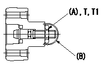
Pump chamber pressure PT, timer stroke TA adjustment procedure
Adjust the sequence in accordance with the procedure below.
1. At N = N1 set PT lower limit at P1.
2. At N = N2, set so that TA lower limit is TA1.
3. At N = N1 tap the regulating valve so that the timer's minimum specifications are obtained.
4. Reconfirm timer specifications for N = N2.
(1)If as specified, confirm timer operation at N = N3.
(2)If not as specified: 1) Readjust the timer at N = N2. (Adjust using the outer adjustable type). 2) Confirm timer operation at N = N1, N = N2.
5. Seal after completing adjustment.
T:Tightening torque
(A) = nut
(B) = sealing wire
----------
N1=1125(r/min) N2=1500(r/min) N3=1850(r/min) P1=235(kPa)(2.4(kgf/cm2)) TA1=2.6(mm)
----------
T1=7~10(N-m)(0.7~1.0(kgf-m))
----------
N1=1125(r/min) N2=1500(r/min) N3=1850(r/min) P1=235(kPa)(2.4(kgf/cm2)) TA1=2.6(mm)
----------
T1=7~10(N-m)(0.7~1.0(kgf-m))
Information:
Repair
Measure crankshaft main journal to main bearing clearance.
Fig. 5-Main Bearing ClearanceMain bearing journal O.D. (new) (1, Fig. 5) ... 3.123 to 3.124 inch(79.32 to 79.35 mm)Assembled Main bearing I.D. (new) (2) ... 3.126 to 3.128 inch(79.39 to 79.45 mm)Main bearing clearance (new) (3) ... 0.0016 to 0.0046 inch(0.041 to 0.117 mm)Main bearing clearance (maximum) ... 0.006 inch(0.15 mm)Main bearing bore I.D. (4) ... 3.325 to 3.326 inch(84.46 to 84.48 mm)Measure crankshaft main journal taper and roundness.
Fig. 6-Main Bearing MeasurementJournal taper (maximum) (1, Fig. 6) ... 0.001 inch per 1.00 inch(0.03 mm per 25.4 mm)Journal out-of-round (maximum) (2, Fig. 6) ... 0.003 inch(0.08 mm)If wear is even, but out of specifications, dress crankshaft main journals and select proper undersize bearing inserts.If journals are out-of-round or tapered, grind crankshaft and select proper undersize bearing inserts.If crankshaft end play is excessive, replace worn thrust bearings or grind crankshaft thrust surfaces and select proper oversize thrust bearing.Installation
Fig. 7-Main Bearing Insert InstallationPosition bearing inserts in cylinder block and main bearing caps with the tang on the insert engaged in the slot in the cylinder block and main bearing caps (Fig. 7).Apply a coat of clean engine oil to the bearing surface of the inserts.Position crankshaft in cylinder block. Tangs on main bearing halves in main bearing caps must be positioned to the same side of the crankshaft as the tangs on main bearing halves in cylinder block.
Fig. 8-Main Bearing Cap PositionsInstall main bearing caps with numbers (1, Fig. 8) corresponding to numbers in oil pan rail (2). If there is no arrow (3) machined on main bearing cap, install cap with number to same side as numbers in oil pan rail. If there is an arrow machined on main bearing cap, arrow must point toward camshaft side.Dip main bearing cap screws in clean engine oil and position them in the main bearing caps. IMPORTANT: Do not use pneumatic wrench to install main bearing cap screws.Before tightening cap screws on main bearing caps, align upper and lower thrust flanges on main thrust bearings. Using a soft-face hammer, tap crankshaft to the rear and then to the front to line up thrust bearing flanges.Rotate crankshaft by hand. Crankshaft should rotate with little effort.
Fig. 9-Main Bearing Cap ScrewTighten main bearing cap screws (Fig. 9)Main bearing cap screw torque ... 85 lb-ft(115 N m) (12 kg-m)Turn crankshaft by hand. If it does not turn easily, disassemble parts and determine the cause.Pull piston and connecting rods into position against the crankshaft.Install connecting rod caps (Group 0403).Install engine front plate (Group 0404).Install camshaft (Group 0402).Install timing gear train (Group 0402).Install timing gear cover (Group 0402).Install vibration damper (Group 0401).Install fan belt and alternator belt (Group 0429).Install flywheel housing (Group 0433).Install flywheel (Group 0433).Install oil pan (Group 0407).Install pushrods and rocker arm assembly (Group 0402).Install rocker arm cover (Group 0402).Install fuel transfer pump (Group 0421).Crankshaft Gear
Removal
Remove crankshaft from engine (Group 0401).
Fig. 10-Crankshaft Gear RemovalUse knife-edge puller (1, Fig. 10) to remove crankshaft gear (2) from