Information injection-pump assembly
ZEXEL
104741-4071
1047414071
NISSAN-DIESEL
1670054T02
1670054t02

Rating:
Components :
| 0. | INJECTION-PUMP ASSEMBLY | 104741-4071 |
| 1. | _ | |
| 2. | FUEL INJECTION PUMP | |
| 3. | NUMBER PLATE | |
| 4. | _ | |
| 5. | CAPSULE | |
| 6. | ADJUSTING DEVICE | |
| 7. | NOZZLE AND HOLDER ASSY | 105118-4780 |
| 8. | Nozzle and Holder | 1660054T00 |
| 9. | Open Pre:MPa(Kqf/cm2) | 18.1(185) |
| 10. | NOZZLE-HOLDER | 105048-3390 |
| 11. | NOZZLE | 105017-0690 |
Include in #2:
104741-4071
as INJECTION-PUMP ASSEMBLY
Cross reference number
ZEXEL
104741-4071
1047414071
NISSAN-DIESEL
1670054T02
1670054t02
Zexel num
Bosch num
Firm num
Name
Calibration Data:
Adjustment conditions
Test oil
1404 Test oil ISO4113orSAEJ967d
1404 Test oil ISO4113orSAEJ967d
Test oil temperature
degC
45
45
50
Nozzle
105780-0060
Bosch type code
NP-DN0SD1510
Nozzle holder
105780-2150
Opening pressure
MPa
13
13
13.3
Opening pressure
kgf/cm2
133
133
136
Injection pipe
157805-7320
Injection pipe
Inside diameter - outside diameter - length (mm) mm 2-6-450
Inside diameter - outside diameter - length (mm) mm 2-6-450
Joint assembly
157641-4720
Tube assembly
157641-4020
Transfer pump pressure
kPa
20
20
20
Transfer pump pressure
kgf/cm2
0.2
0.2
0.2
Direction of rotation (viewed from drive side)
Right R
Right R
Injection timing adjustment
Pump speed
r/min
1000
1000
1000
Average injection quantity
mm3/st.
57.4
56.9
57.9
Difference in delivery
mm3/st.
4.5
Basic
*
Injection timing adjustment_02
Pump speed
r/min
2150
2150
2150
Average injection quantity
mm3/st.
20
16.5
23.5
Injection timing adjustment_03
Pump speed
r/min
1900
1900
1900
Average injection quantity
mm3/st.
61.4
56.9
65.9
Injection timing adjustment_04
Pump speed
r/min
1500
1500
1500
Average injection quantity
mm3/st.
60.2
56.7
63.7
Injection timing adjustment_05
Pump speed
r/min
1000
1000
1000
Average injection quantity
mm3/st.
57.4
56.4
58.4
Injection timing adjustment_06
Pump speed
r/min
750
750
750
Average injection quantity
mm3/st.
49.2
45.7
52.7
Injection timing adjustment_07
Pump speed
r/min
500
500
500
Average injection quantity
mm3/st.
45.1
41.1
49.1
Injection timing adjustment_08
Pump speed
r/min
400
400
400
Average injection quantity
mm3/st.
50.8
45.3
56.3
Injection quantity adjustment
Pump speed
r/min
2150
2150
2150
Average injection quantity
mm3/st.
20
17
23
Difference in delivery
mm3/st.
5.5
Basic
*
Injection quantity adjustment_02
Pump speed
r/min
2300
2300
2300
Average injection quantity
mm3/st.
8
Governor adjustment
Pump speed
r/min
350
350
350
Average injection quantity
mm3/st.
9.8
7.8
11.8
Difference in delivery
mm3/st.
2
Basic
*
Governor adjustment_02
Pump speed
r/min
300
300
300
Average injection quantity
mm3/st.
15.1
10.1
20.1
Governor adjustment_03
Pump speed
r/min
350
350
350
Average injection quantity
mm3/st.
9.8
7.8
11.8
Governor adjustment_04
Pump speed
r/min
500
500
500
Average injection quantity
mm3/st.
5
Timer adjustment
Pump speed
r/min
100
100
100
Average injection quantity
mm3/st.
80
60
100
Basic
*
Speed control lever angle
Pump speed
r/min
350
350
350
Average injection quantity
mm3/st.
0
0
0
Remarks
Magnet OFF
Magnet OFF
0000000901
Pump speed
r/min
1000
1000
1000
Overflow quantity
cm3/min
339
210
468
Stop lever angle
Pump speed
r/min
1000
1000
1000
Pressure
kPa
294
284
304
Pressure
kgf/cm2
3
2.9
3.1
Basic
*
Stop lever angle_02
Pump speed
r/min
1000
1000
1000
Pressure
kPa
294
284
304
Pressure
kgf/cm2
3
2.9
3.1
Stop lever angle_03
Pump speed
r/min
1500
1500
1500
Pressure
kPa
392
343
441
Pressure
kgf/cm2
4
3.5
4.5
Stop lever angle_04
Pump speed
r/min
1900
1900
1900
Pressure
kPa
588.5
510
667
Pressure
kgf/cm2
6
5.2
6.8
0000001101
Pump speed
r/min
1500
1500
1500
Timer stroke
mm
2.8
2.6
3
Basic
*
_02
Pump speed
r/min
1500
1500
1500
Timer stroke
mm
2.8
2.6
3
_03
Pump speed
r/min
1900
1900
1900
Timer stroke
mm
6.15
5.7
6.6
0000001201
Max. applied voltage
V
8
8
8
Test voltage
V
13
12
14
Timing setting
K dimension
mm
3.1
3
3.2
KF dimension
mm
5.5
5.4
5.6
MS dimension
mm
0.7
0.6
0.8
Pre-stroke
mm
0.45
0.43
0.47
Control lever angle alpha
deg.
25
21
29
Control lever angle beta
deg.
36
31
41
Test data Ex:
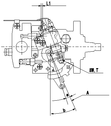
0000001801 ACCELERATOR SWITCH ADJ

Adjustment of the accelerator switch
ON - OFF changeover point: from idle to c (shim thickness L1 mm)
Idle-d: ON
e-full: OFF
A = idle lever position
----------
c=4+-2deg d=4deg e=4deg L1=2.7+-0.13mm
----------
SW=SW10 T=6~9N-m(0.6~0.9kgf-m) a=4+-2deg b=(25+-2deg) L1=(2.7mm)
----------
c=4+-2deg d=4deg e=4deg L1=2.7+-0.13mm
----------
SW=SW10 T=6~9N-m(0.6~0.9kgf-m) a=4+-2deg b=(25+-2deg) L1=(2.7mm)
Information:
PARTS NEEDED
Qty
Part Number Description
6 1R6573 GASKET
1 2941706 GASKET
6 2941788 SEAL
1 2941790 PIPE
1 2941791 PIPE
1 2941792 PIPE
1 2941793 PIPE
1 2941794 PIPE
1 2941795 PIPE
6 2941803 SEAL-O-RING
6 3264756 INJECTOR GP-F -G
1 3280972 SOFTWARE GP-ELEK
In order to allow equitable parts availability to all participating dealers, please limit your initial parts order to not exceed 2% of dealership population. This is an initial order recommendation only, and the ultimate responsibility for ordering the total number of parts needed to satisfy the program lies with the dealer.
ACTION REQUIRED
If your engine is experiencing a lack of power and/or black smoke emissions, complete the following actions:
- Replace the six fuel injectors at the time of repair. Replace the existing unit injectors with the new 326-4756 Fuel Injector Groups. Refer to KENR8106, Disassembly and Assembly, for removal/install procedure of the fuel injector groups.
- Flash the new engine 328-0972 Software Group. The new engine software will change the engine power and therefore it is needed to request a Factory Password before flashing.
SERVICE CLAIM ALLOWANCES
Product smu/age whichever comes first Caterpillar Dealer Suggested Customer Suggested
Parts % Labor Hrs% Parts % Labor Hrs% Parts % Labor Hrs%
0-4000 hrs,
0-60 mo 100.0% 100.0% 0.0% 0.0% 0.0% 0.0%
4001-6000 hrs,
61-90 mo 33.0% 50.0% 0.0% 0.0% 50.0% 50.0%
This is a 4.0-hour job
PARTS DISPOSITION
Handle the parts in accordance with your Warranty Bulletin on warranty parts handling.