Information injection-pump assembly
ZEXEL
104741-3791
1047413791
Rating:
Cross reference number
ZEXEL
104741-3791
1047413791
Zexel num
Bosch num
Firm num
Name
104741-3791
INJECTION-PUMP ASSEMBLY
11CJ VE4 VE
11CJ VE4 VE
Calibration Data:
Adjustment conditions
Test oil
1404 Test oil ISO4113orSAEJ967d
1404 Test oil ISO4113orSAEJ967d
Test oil temperature
degC
45
45
50
Nozzle
105780-0060
Bosch type code
NP-DN0SD1510
Nozzle holder
105780-2150
Opening pressure
MPa
13
13
13.3
Opening pressure
kgf/cm2
133
133
136
Injection pipe
157805-7320
Injection pipe
Inside diameter - outside diameter - length (mm) mm 2-6-450
Inside diameter - outside diameter - length (mm) mm 2-6-450
Joint assembly
157641-4720
Tube assembly
157641-4020
Transfer pump pressure
kPa
20
20
20
Transfer pump pressure
kgf/cm2
0.2
0.2
0.2
Direction of rotation (viewed from drive side)
Right R
Right R
Injection timing adjustment
Pump speed
r/min
750
750
750
Boost pressure
kPa
0
0
0
Boost pressure
kgf/cm2
0
0
0
Boost pressure
mmHg
0
0
0
Average injection quantity
mm3/st.
48.5
48
49
Difference in delivery
mm3/st.
4.5
Basic
*
Oil temperature
degC
50
48
52
Remarks
NA
NA
Injection timing adjustment_02
Pump speed
r/min
750
750
750
Boost pressure
kPa
46.7
45.4
48
Boost pressure
kgf/cm2
0.48
0.466
0.494
Boost pressure
mmHg
350
340
360
Average injection quantity
mm3/st.
65.4
64.9
65.9
Difference in delivery
mm3/st.
5.5
Basic
*
Oil temperature
degC
50
48
52
Remarks
CBS
CBS
Injection timing adjustment_03
Pump speed
r/min
1000
1000
1000
Boost pressure
kPa
86.6
85.3
87.9
Boost pressure
kgf/cm2
0.88
0.866
0.894
Boost pressure
mmHg
650
640
660
Average injection quantity
mm3/st.
81.1
80.6
81.6
Difference in delivery
mm3/st.
6.5
Basic
*
Oil temperature
degC
50
48
52
Remarks
Full
Full
Injection timing adjustment_04
Pump speed
r/min
750
750
750
Boost pressure
kPa
0
0
0
Boost pressure
kgf/cm2
0
0
0
Boost pressure
mmHg
0
0
0
Average injection quantity
mm3/st.
48.5
47.5
49.5
Basic
*
Oil temperature
degC
50
48
52
Remarks
NA
NA
Injection timing adjustment_05
Pump speed
r/min
750
750
750
Boost pressure
kPa
46.7
45.4
48
Boost pressure
kgf/cm2
0.48
0.466
0.494
Boost pressure
mmHg
350
340
360
Average injection quantity
mm3/st.
65.4
64.4
66.4
Basic
*
Oil temperature
degC
50
48
52
Remarks
CBS
CBS
Injection timing adjustment_06
Pump speed
r/min
1000
1000
1000
Boost pressure
kPa
86.6
85.3
87.9
Boost pressure
kgf/cm2
0.88
0.866
0.894
Boost pressure
mmHg
650
640
660
Average injection quantity
mm3/st.
81.1
80.1
82.1
Difference in delivery
mm3/st.
7
Basic
*
Oil temperature
degC
50
48
52
Remarks
Full
Full
Injection timing adjustment_07
Pump speed
r/min
2000
2000
2000
Boost pressure
kPa
86.6
85.3
87.9
Boost pressure
kgf/cm2
0.88
0.866
0.894
Boost pressure
mmHg
650
640
660
Average injection quantity
mm3/st.
68.6
64.6
72.6
Oil temperature
degC
50
48
52
Injection quantity adjustment
Pump speed
r/min
2475
2475
2475
Boost pressure
kPa
86.6
85.3
87.9
Boost pressure
kgf/cm2
0.88
0.866
0.894
Boost pressure
mmHg
650
640
660
Average injection quantity
mm3/st.
26.4
23.4
29.4
Difference in delivery
mm3/st.
8
Basic
*
Oil temperature
degC
55
52
58
Injection quantity adjustment_02
Pump speed
r/min
3000
3000
3000
Boost pressure
kPa
86.6
85.3
87.9
Boost pressure
kgf/cm2
0.88
0.866
0.894
Boost pressure
mmHg
650
640
660
Average injection quantity
mm3/st.
8
Oil temperature
degC
55
52
58
Injection quantity adjustment_03
Pump speed
r/min
2475
2475
2475
Boost pressure
kPa
86.6
85.3
87.9
Boost pressure
kgf/cm2
0.88
0.866
0.894
Boost pressure
mmHg
650
640
660
Average injection quantity
mm3/st.
26.4
21.4
31.4
Difference in delivery
mm3/st.
8.5
Basic
*
Oil temperature
degC
55
52
58
Governor adjustment
Pump speed
r/min
400
400
400
Boost pressure
kPa
0
0
0
Boost pressure
kgf/cm2
0
0
0
Boost pressure
mmHg
0
0
0
Average injection quantity
mm3/st.
18.9
16.9
20.9
Difference in delivery
mm3/st.
2
Basic
*
Oil temperature
degC
48
46
50
Governor adjustment_02
Pump speed
r/min
400
400
400
Boost pressure
kPa
0
0
0
Boost pressure
kgf/cm2
0
0
0
Boost pressure
mmHg
0
0
0
Average injection quantity
mm3/st.
18.9
16.4
21.4
Difference in delivery
mm3/st.
2.5
Basic
*
Oil temperature
degC
48
46
50
Governor adjustment_03
Pump speed
r/min
750
750
750
Boost pressure
kPa
0
0
0
Boost pressure
kgf/cm2
0
0
0
Boost pressure
mmHg
0
0
0
Average injection quantity
mm3/st.
5
Oil temperature
degC
50
48
52
Timer adjustment
Pump speed
r/min
100
100
100
Boost pressure
kPa
0
0
0
Boost pressure
kgf/cm2
0
0
0
Boost pressure
mmHg
0
0
0
Average injection quantity
mm3/st.
91.7
71.7
111.7
Basic
*
Oil temperature
degC
48
46
50
Remarks
IDLE
IDLE
Timer adjustment_02
Pump speed
r/min
100
100
100
Boost pressure
kPa
0
0
0
Boost pressure
kgf/cm2
0
0
0
Boost pressure
mmHg
0
0
0
Average injection quantity
mm3/st.
91.7
71.7
111.7
Oil temperature
degC
48
46
50
Remarks
IDLE
IDLE
Speed control lever angle
Pump speed
r/min
400
400
400
Boost pressure
kPa
0
0
0
Boost pressure
kgf/cm2
0
0
0
Boost pressure
mmHg
0
0
0
Average injection quantity
mm3/st.
0
0
0
Oil temperature
degC
48
46
50
Remarks
Magnet OFF at idling position
Magnet OFF at idling position
0000000901
Pump speed
r/min
1250
1250
1250
Boost pressure
kPa
86.6
85.3
87.9
Boost pressure
kgf/cm2
0.88
0.866
0.894
Boost pressure
mmHg
650
640
660
Overflow quantity with S/T ON
cm3/min
670
540
800
Oil temperature
degC
50
48
52
Stop lever angle
Pump speed
r/min
1500
1500
1500
Boost pressure
kPa
86.6
85.3
87.9
Boost pressure
kgf/cm2
0.88
0.866
0.894
Boost pressure
mmHg
650
640
660
Pressure with S/T ON
kPa
647
608
686
Pressure with S/T ON
kgf/cm2
6.6
6.2
7
Pressure with S/T OFF
kPa
600
580
620
Pressure with S/T OFF
kgf/cm2
5.1
4.9
5.3
Basic
*
Oil temperature
degC
50
48
52
Remarks
OFF
OFF
0000001101
Pump speed
r/min
1500
1500
1500
Boost pressure
kPa
86.6
85.3
87.9
Boost pressure
kgf/cm2
0.88
0.866
0.894
Boost pressure
mmHg
650
640
660
Timer stroke with S/T ON
mm
6.8
5.3
8.3
Timer stroke with S/T OFF
mm
3.4
3.2
3.6
Basic
*
Oil temperature
degC
50
48
52
Remarks
OFF
OFF
_02
Pump speed
r/min
1000
1000
1000
Boost pressure
kPa
86.6
85.3
87.9
Boost pressure
kgf/cm2
0.88
0.866
0.894
Boost pressure
mmHg
650
640
660
Timer stroke with S/T ON
mm
3.9
3.2
4.6
Timer stroke with S/T OFF
mm
1
Oil temperature
degC
50
48
52
_03
Pump speed
r/min
1250
1250
1250
Boost pressure
kPa
86.6
85.3
87.9
Boost pressure
kgf/cm2
0.88
0.866
0.894
Boost pressure
mmHg
650
640
660
Timer stroke with S/T OFF
mm
2
1.3
2.7
Oil temperature
degC
50
48
52
_04
Pump speed
r/min
1500
1500
1500
Boost pressure
kPa
86.6
85.3
87.9
Boost pressure
kgf/cm2
0.88
0.866
0.894
Boost pressure
mmHg
650
640
660
Timer stroke with S/T ON
mm
6.8
6.1
7.5
Timer stroke with S/T OFF
mm
3.4
2
4.8
Basic
*
Oil temperature
degC
50
48
52
Remarks
OFF
OFF
_05
Pump speed
r/min
2000
2000
2000
Boost pressure
kPa
86.6
85.3
87.9
Boost pressure
kgf/cm2
0.88
0.866
0.894
Boost pressure
mmHg
650
640
660
Timer stroke with S/T OFF
mm
6.3
5.6
7
Oil temperature
degC
50
48
52
_06
Pump speed
r/min
2300
2300
2300
Boost pressure
kPa
86.6
85.3
87.9
Boost pressure
kgf/cm2
0.88
0.866
0.894
Boost pressure
mmHg
650
640
660
Timer stroke with S/T ON
mm
8.6
8.1
9
Timer stroke with S/T OFF
mm
8
7.3
8.7
Oil temperature
degC
52
50
54
0000001201
Max. applied voltage
V
8
8
8
Test voltage
V
13
12
14
Timing setting
K dimension
mm
3.3
3.2
3.4
KF dimension
mm
5.8
5.7
5.9
MS dimension
mm
0.6
0.5
0.7
BCS stroke
mm
6.8
6.6
7
Control lever angle alpha
deg.
59
55
63
Control lever angle beta
deg.
40
35
45
Test data Ex:
0000001801 POTENTIOMETER ADJUSTMENT
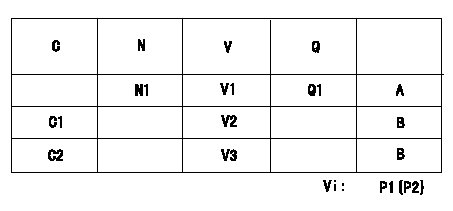
Adjustment of the potentiometer
Adjusting method (service voltage Vi, dummy bolt):
1. Hold the dummy bolt against the control lever when N = N1 r/min, Q = Q1 mm3/st.
Fix using the lock nut.
2. When adjusting the potentiometer, position the control lever against the dummy bolt and adjust the potentiometer so that the output voltage is V1 (V).
3. Remove the dummy bolt after the completion of adjustment.
Confirm that the potentiometer output voltage is within the standards mentioned when the control lever is idling and in full-speed position.
Vi:Applied voltage
C:Position of the control lever
N:Pump speed (r/min)
V:Output voltage (V)
Q:Injection quantity (mm3/st)
A:Adjusting point
B:Checking point
C1:Idling
C2:Full speed
P1:Boost pressure
P2:Boost pressure
----------
N1=750r/min V1=4.16+-0.03V Q1=34.7+-1.0cm3/1,000st
----------
N1=750r/min V1=4.16+-0.03V V2=2.16+-0.52V V3=9.02+-0.72V Q1=34.7+-1.0cm3/1,000st Vi=10V P1=0kPa P2=0mmHg
----------
N1=750r/min V1=4.16+-0.03V Q1=34.7+-1.0cm3/1,000st
----------
N1=750r/min V1=4.16+-0.03V V2=2.16+-0.52V V3=9.02+-0.72V Q1=34.7+-1.0cm3/1,000st Vi=10V P1=0kPa P2=0mmHg
0000001901 W-CSD ADJUSTMENT
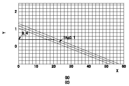
Adjustment of the W-CSD
1. Adjustment of the advance angle of the timer
(1)Determine the timer advance angle using the following graph.
(2)(1) Adjust with the screw (A) so that the timer advance angle determined in the item (1) is obtained.
X:Temperature t (deg C)
Y:Timer stroke TA (mm)
(B): Timer stroke TA (mm):
----------
----------
(B)=TA=-0.04t+1.2(0<=t<=30)
----------
----------
(B)=TA=-0.04t+1.2(0<=t<=30)
0000002001 W-FICD LEVER ADJUSTMENT
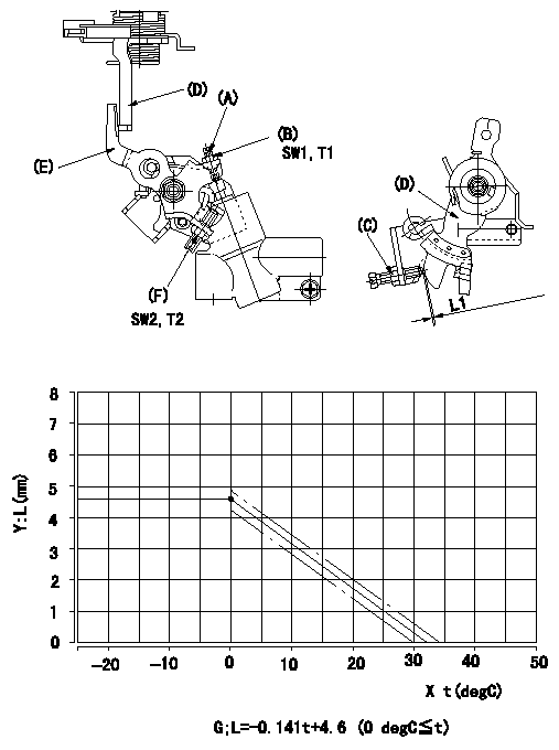
2. Adjustment of the W-FICD
(1)Insert a block gauge L1 determined from the graph below between the control lever (D) and the idle set screw (C).
(2)Tighten the nut (F) at the position where the W-FICD lever (E) the control lever (D) contact.
T2T2
(3)After adjusting the W-FICD lever (E), confirm that the timer stroke is the value adjusted in item 1. Then, remove the shim.
Y = control lever position
X = temperature
G = control lever position: (mm)
----------
L1=L+-0.3 mm T2=6~9 N-m{0.6~0.9 kgf-m}
----------
L1=L+-0.3 mm SW2=SW10 T2=6~9 N-m{0.6~0.9 kgf-m} SW1=SW8 T1=3.4~4.9 N-m{0.35~0.5 kgf-m}
----------
L1=L+-0.3 mm T2=6~9 N-m{0.6~0.9 kgf-m}
----------
L1=L+-0.3 mm SW2=SW10 T2=6~9 N-m{0.6~0.9 kgf-m} SW1=SW8 T1=3.4~4.9 N-m{0.35~0.5 kgf-m}
Information:
To Remove the Flywheel
1. Remove the gearbox and flywheel housing.2. Remove clutch assembly.3. Remove the flywheel (see Note). With some applications, the flywheel is secured to the crankshaft with 12 setscrews and washers.4. Remove the clutch pilot bearing (if fitted). To facilitate safe flywheel removal, remove two diametrically opposed securing setscrews and in their place, fit two suitably sized studs, finger tight only. The remaining setscrews can now be removed and the flywheel withdrawn under control.To Renew the Flywheel Ring Gear
1. Place the flywheel in a suitable container of clean cold water and support it by positioning four metal blocks under the ring gear. Arrange the flywheel assembly so that, when placed in the water the ring gear is uppermost and clear of the water line by approximately 1/4 in (6,5 mm). Heat the ring gear evenly around its circumference, thus expanding it. This will allow the flywheel to drop away from the ring gear.2. Heat the new ring gear to an approximate temperature of 475°F (246°C). Fit the gear over the flywheel with the lead-in on the teeth facing towards the front of the flywheel and allow the ring to cool.To Refit the Flywheel
1. Using the method of removal but in reverse, mount the flywheel to the crankshaft flange so that the untapped hole in the flange is in line with the seventh unused smaller hole in the flywheel.2. Engage the securing setscrews with new hardened steel washers and tighten to a torque of 80 lbf ft (11,0 kfg m) -108 Nm. Where the flywheel is secured with place bolts, without washers, these should be tightened to 90 lbf ft (12,4 kgf m) - 122 Nm. Place bolts can be identified by the 6 slots cut in the head face and the embossed letter 'T'.3. Set up a clock indicator gauge with the base secured to the flywheel housing or cylinder block and adjust the clock so that the stylus is contacting the flywheel periphery. Turn the crankshaft and check the total reading. The flywheel should run true within 0.012 in (0,30 mm) total indicator reading.
P14. Now adjust the clock gauge so that the plunger is at right angles to the crankshaft flange and rests on the vertical machined face of the flywheel, at the outermost point of the face (Fig. P.1). Press the crankshaft one way to take up the end float, and turn the flywheel. The run-out on the flywheel face should be within 0.001 in (0,025 mm) per inch (25 mm) of flywheel radius from the crankshaft axis to the clock gauge stylus. If not, remove flywheel and check mating faces for burrs and dirt.5. Lock the setscrews with the tab washers where fitted.6. Refit the clutch and gearbox, etc.To Remove the Flywheel Housing
1. Remove the flywheel.2. Unscrew the nuts or setscrews securing the flywheel housing
Have questions with 104741-3791?
Group cross 104741-3791 ZEXEL
Mitsubishi
Mitsubishi
Mitsubishi
Mitsubishi
Mitsubishi
Mitsubishi
Mitsubishi
Mitsubishi
104741-3791
INJECTION-PUMP ASSEMBLY