Information injection-pump assembly
BOSCH
9 460 613 497
9460613497
ZEXEL
104741-3790
1047413790
Rating:
Cross reference number
BOSCH
9 460 613 497
9460613497
ZEXEL
104741-3790
1047413790
Zexel num
Bosch num
Firm num
Name
Calibration Data:
Adjustment conditions
Test oil
1404 Test oil ISO4113orSAEJ967d
1404 Test oil ISO4113orSAEJ967d
Test oil temperature
degC
45
45
50
Nozzle
105780-0060
Bosch type code
NP-DN0SD1510
Nozzle holder
105780-2150
Opening pressure
MPa
13
13
13.3
Opening pressure
kgf/cm2
133
133
136
Injection pipe
157805-7320
Injection pipe
Inside diameter - outside diameter - length (mm) mm 2-6-450
Inside diameter - outside diameter - length (mm) mm 2-6-450
Joint assembly
157641-4720
Tube assembly
157641-4020
Transfer pump pressure
kPa
20
20
20
Transfer pump pressure
kgf/cm2
0.2
0.2
0.2
Direction of rotation (viewed from drive side)
Right R
Right R
Injection timing adjustment
Pump speed
r/min
750
750
750
Boost pressure
kPa
0
0
0
Boost pressure
kgf/cm2
0
0
0
Boost pressure
mmHg
0
0
0
Average injection quantity
mm3/st.
48.5
48
49
Difference in delivery
mm3/st.
4.5
Basic
*
Oil temperature
degC
50
48
52
Remarks
NA
NA
Injection timing adjustment_02
Pump speed
r/min
750
750
750
Boost pressure
kPa
46.7
45.4
48
Boost pressure
kgf/cm2
0.48
0.466
0.494
Boost pressure
mmHg
350
340
360
Average injection quantity
mm3/st.
65.4
64.9
65.9
Difference in delivery
mm3/st.
5.5
Basic
*
Oil temperature
degC
50
48
52
Remarks
CBS
CBS
Injection timing adjustment_03
Pump speed
r/min
1000
1000
1000
Boost pressure
kPa
86.6
85.3
87.9
Boost pressure
kgf/cm2
0.88
0.866
0.894
Boost pressure
mmHg
650
640
660
Average injection quantity
mm3/st.
81.1
80.6
81.6
Difference in delivery
mm3/st.
6.5
Basic
*
Oil temperature
degC
50
48
52
Remarks
Full
Full
Injection timing adjustment_04
Pump speed
r/min
750
750
750
Boost pressure
kPa
0
0
0
Boost pressure
kgf/cm2
0
0
0
Boost pressure
mmHg
0
0
0
Average injection quantity
mm3/st.
48.5
47.5
49.5
Basic
*
Oil temperature
degC
50
48
52
Remarks
NA
NA
Injection timing adjustment_05
Pump speed
r/min
750
750
750
Boost pressure
kPa
46.7
45.4
48
Boost pressure
kgf/cm2
0.48
0.466
0.494
Boost pressure
mmHg
350
340
360
Average injection quantity
mm3/st.
65.4
64.4
66.4
Basic
*
Oil temperature
degC
50
48
52
Remarks
CBS
CBS
Injection timing adjustment_06
Pump speed
r/min
1000
1000
1000
Boost pressure
kPa
86.6
85.3
87.9
Boost pressure
kgf/cm2
0.88
0.866
0.894
Boost pressure
mmHg
650
640
660
Average injection quantity
mm3/st.
81.1
80.1
82.1
Difference in delivery
mm3/st.
7
Basic
*
Oil temperature
degC
50
48
52
Remarks
Full
Full
Injection timing adjustment_07
Pump speed
r/min
2000
2000
2000
Boost pressure
kPa
86.6
85.3
87.9
Boost pressure
kgf/cm2
0.88
0.866
0.894
Boost pressure
mmHg
650
640
660
Average injection quantity
mm3/st.
68.6
64.6
72.6
Oil temperature
degC
50
48
52
Injection quantity adjustment
Pump speed
r/min
2475
2475
2475
Boost pressure
kPa
86.6
85.3
87.9
Boost pressure
kgf/cm2
0.88
0.866
0.894
Boost pressure
mmHg
650
640
660
Average injection quantity
mm3/st.
26.4
23.4
29.4
Difference in delivery
mm3/st.
8
Basic
*
Oil temperature
degC
55
52
58
Injection quantity adjustment_02
Pump speed
r/min
3000
3000
3000
Boost pressure
kPa
86.6
85.3
87.9
Boost pressure
kgf/cm2
0.88
0.866
0.894
Boost pressure
mmHg
650
640
660
Average injection quantity
mm3/st.
8
Oil temperature
degC
55
52
58
Injection quantity adjustment_03
Pump speed
r/min
2475
2475
2475
Boost pressure
kPa
86.6
85.3
87.9
Boost pressure
kgf/cm2
0.88
0.866
0.894
Boost pressure
mmHg
650
640
660
Average injection quantity
mm3/st.
26.4
21.4
31.4
Difference in delivery
mm3/st.
8.5
Basic
*
Oil temperature
degC
55
52
58
Governor adjustment
Pump speed
r/min
400
400
400
Boost pressure
kPa
0
0
0
Boost pressure
kgf/cm2
0
0
0
Boost pressure
mmHg
0
0
0
Average injection quantity
mm3/st.
18.9
16.9
20.9
Difference in delivery
mm3/st.
2
Basic
*
Oil temperature
degC
48
46
50
Governor adjustment_02
Pump speed
r/min
400
400
400
Boost pressure
kPa
0
0
0
Boost pressure
kgf/cm2
0
0
0
Boost pressure
mmHg
0
0
0
Average injection quantity
mm3/st.
18.9
16.4
21.4
Difference in delivery
mm3/st.
2.5
Basic
*
Oil temperature
degC
48
46
50
Governor adjustment_03
Pump speed
r/min
750
750
750
Boost pressure
kPa
0
0
0
Boost pressure
kgf/cm2
0
0
0
Boost pressure
mmHg
0
0
0
Average injection quantity
mm3/st.
5
Oil temperature
degC
50
48
52
Timer adjustment
Pump speed
r/min
100
100
100
Boost pressure
kPa
0
0
0
Boost pressure
kgf/cm2
0
0
0
Boost pressure
mmHg
0
0
0
Average injection quantity
mm3/st.
91.7
71.7
111.7
Oil temperature
degC
48
46
50
Remarks
IDLE
IDLE
Timer adjustment_02
Pump speed
r/min
100
100
100
Boost pressure
kPa
0
0
0
Boost pressure
kgf/cm2
0
0
0
Boost pressure
mmHg
0
0
0
Average injection quantity
mm3/st.
91.7
71.7
111.7
Oil temperature
degC
48
46
50
Remarks
IDLE
IDLE
Speed control lever angle
Pump speed
r/min
400
400
400
Boost pressure
kPa
0
0
0
Boost pressure
kgf/cm2
0
0
0
Boost pressure
mmHg
0
0
0
Average injection quantity
mm3/st.
0
0
0
Oil temperature
degC
48
46
50
Remarks
Magnet OFF at idling position
Magnet OFF at idling position
0000000901
Pump speed
r/min
1250
1250
1250
Boost pressure
kPa
86.6
85.3
87.9
Boost pressure
kgf/cm2
0.88
0.866
0.894
Boost pressure
mmHg
650
640
660
Overflow quantity with S/T ON
cm3/min
670
540
800
Oil temperature
degC
50
48
52
Stop lever angle
Pump speed
r/min
1500
1500
1500
Boost pressure
kPa
86.6
85.3
87.9
Boost pressure
kgf/cm2
0.88
0.866
0.894
Boost pressure
mmHg
650
640
660
Pressure with S/T ON
kPa
647
608
686
Pressure with S/T ON
kgf/cm2
6.6
6.2
7
Pressure with S/T OFF
kPa
500
480
520
Pressure with S/T OFF
kgf/cm2
5.1
4.9
5.3
Basic
*
Oil temperature
degC
50
48
52
Remarks
OFF
OFF
0000001101
Pump speed
r/min
1500
1500
1500
Boost pressure
kPa
86.6
85.3
87.9
Boost pressure
kgf/cm2
0.88
0.866
0.894
Boost pressure
mmHg
650
640
660
Timer stroke with S/T ON
mm
6.8
6.3
7.3
Timer stroke with S/T OFF
mm
3.4
3.2
3.6
Basic
*
Oil temperature
degC
50
48
52
Remarks
OFF
OFF
_02
Pump speed
r/min
1000
1000
1000
Boost pressure
kPa
86.6
85.3
87.9
Boost pressure
kgf/cm2
0.88
0.866
0.894
Boost pressure
mmHg
650
640
660
Timer stroke with S/T ON
mm
3.9
3.2
4.6
Timer stroke with S/T OFF
mm
1
Oil temperature
degC
50
48
52
_03
Pump speed
r/min
1250
1250
1250
Boost pressure
kPa
86.6
85.3
87.9
Boost pressure
kgf/cm2
0.88
0.866
0.894
Boost pressure
mmHg
650
640
660
Timer stroke with S/T OFF
mm
2
1.3
2.7
Oil temperature
degC
50
48
52
_04
Pump speed
r/min
1500
1500
1500
Boost pressure
kPa
86.6
85.3
87.9
Boost pressure
kgf/cm2
0.88
0.866
0.894
Boost pressure
mmHg
650
640
660
Timer stroke with S/T ON
mm
6.8
6.1
7.5
Timer stroke with S/T OFF
mm
3.4
3
3.8
Basic
*
Oil temperature
degC
50
48
52
Remarks
OFF
OFF
_05
Pump speed
r/min
2000
2000
2000
Boost pressure
kPa
86.6
85.3
87.9
Boost pressure
kgf/cm2
0.88
0.866
0.894
Boost pressure
mmHg
650
640
660
Timer stroke with S/T OFF
mm
6.3
5.6
7
Oil temperature
degC
50
48
52
_06
Pump speed
r/min
2300
2300
2300
Boost pressure
kPa
86.6
85.3
87.9
Boost pressure
kgf/cm2
0.88
0.866
0.894
Boost pressure
mmHg
650
640
660
Timer stroke with S/T ON
mm
8.6
8.1
9
Timer stroke with S/T OFF
mm
8
7.3
8.7
Oil temperature
degC
52
50
54
0000001201
Max. applied voltage
V
8
8
8
Test voltage
V
13
12
14
Timing setting
K dimension
mm
3.3
3.2
3.4
KF dimension
mm
5.8
5.7
5.9
MS dimension
mm
0.6
0.5
0.7
BCS stroke
mm
6.8
6.6
7
Control lever angle alpha
deg.
59
55
63
Control lever angle beta
deg.
40
35
45
Test data Ex:
0000001801 W-CSD ADJUSTMENT
Adjustment of the W-CSD
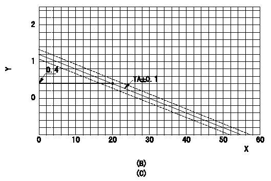
1. Adjustment of the advance angle of the timer
(1)Determine the timer advance angle using the following graph.
(2)(1) Adjust with the screw (A) so that the timer advance angle determined in the item (1) is obtained.
X:Temperature t (deg C)
Y:Timer stroke TA (mm)
(B): Timer stroke TA (mm):
----------
----------
(B)=TAmm (C)=TA=-0.04t+1.2{0<=t<=30(degC)} X=tdegC Y=TAmm
----------
----------
(B)=TAmm (C)=TA=-0.04t+1.2{0<=t<=30(degC)} X=tdegC Y=TAmm
0000001901 POTENTIOMETER ADJUSTMENT
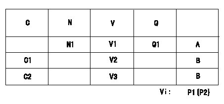
Adjustment of the potentiometer
Adjusting method (service voltage Vi, dummy bolt):
1. Hold the dummy bolt against the control lever when N = N1 r/min, Q = Q1 mm3/st.
Fix using the lock nut.
2. When adjusting the potentiometer, position the control lever against the dummy bolt and adjust the potentiometer so that the output voltage is V1 (V).
3. Remove the dummy bolt after the completion of adjustment.
Confirm that the potentiometer output voltage is within the standards mentioned when the control lever is idling and in full-speed position.
Vi:Applied voltage
C:Position of the control lever
N:Pump speed (r/min)
V:Output voltage (V)
Q:Injection quantity (mm3/st)
A:Adjusting point
B:Checking point
C1:Idling
C2:Full speed
P1:Boost pressure
P2:Boost pressure
----------
N1=750r/min V1=4.16+-0.03V Q1=34.7+-1.0cm3/1,000st
----------
N1=750(r/min) V1=4.16+-0.03(V) V2=(2.16+-0.52)(V) V3=(9.02+-0.72)(V) Q1=34.7+-1.0(cm3/1,000st) Vi=10V
----------
N1=750r/min V1=4.16+-0.03V Q1=34.7+-1.0cm3/1,000st
----------
N1=750(r/min) V1=4.16+-0.03(V) V2=(2.16+-0.52)(V) V3=(9.02+-0.72)(V) Q1=34.7+-1.0(cm3/1,000st) Vi=10V
0000002001
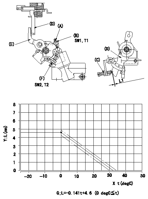
2. Adjustment of the W-FICD
(1)Insert a block gauge L1 determined from the graph below between the control lever (D) and the idle set screw (C).
(2)Tighten the nut (F) at the position where the W-FICD lever (E) the control lever (D) contact.
T2T2
(3)After adjusting the W-FICD lever (E), confirm that the timer stroke is the value adjusted in item 1. Then, remove the shim.
Y = control lever position
X = temperature
G = control lever position: (mm)
----------
L1=L+-0.3 mm T2=6~9 N-m{0.6~0.9 kgf-m}
----------
L1=L+-0.3 mm SW2=SW10 T2=6~9 N-m{0.6~0.9 kgf-m} SW1=SW8 T1=3.4~4.9 N-m{0.35~0.5 kgf-m}
----------
L1=L+-0.3 mm T2=6~9 N-m{0.6~0.9 kgf-m}
----------
L1=L+-0.3 mm SW2=SW10 T2=6~9 N-m{0.6~0.9 kgf-m} SW1=SW8 T1=3.4~4.9 N-m{0.35~0.5 kgf-m}
Information:
* Check that there is continuity between each stator lead.* If there is no continuity, the lead has broken.(2) Continuity between each lead wires and the core * Check that there is no continuity between lead wires and the core.* If there is continuity, the lead wire has short-circuited. Inspection: Brush* If the length of the brush has reached wear limit, replace the brush. Inspection: Rectifier* Check the function of diodes within rectifier properly. If any fault is found, replace the rectifier. If resistance is infinite in both cases, the diode is open.If resistance is close to 0 ohms in both cases, the diode is shorted.A, B, C: Lead connecting area of stator coilD, F: Heat sink areaE: Regulator connecting area* Inspection should be conducted twice, changed over the positive probe and the negative probe of the tester.* When inspecting using a tester, the current flowing through the rectifier is smaller than usual. Therefore, an incorrect resistance value may be indicated on the tester. Additionally, incorrect indications become larger as the range of the tester gets smaller. Set the tester to the largest possible scale. Assembly Procedure Assembly: Regulator and brush holder* To install the regulator and brush holder, follow the disassembly sequence in reverse. (See " Disassembly: Regulator and brush holder".) Assembly: Brush * Install brush on regulator and brush holder in the direction as illustrated.* After installation, solder the lead wire of brush on the regulator and brush holder. Thereafter, fit the cover as it was. Assembly: Stator* To install the stator, follow the disassembly sequence in reverse. (See " Disassembly: Stator".) Assembly: Rotor and rear bracket * If brush protrudes from regulator and brush holder, rotor cannot be installed onto the rear bracket. In this case, do the following:* Push brush into regulator and brush holder.* Insert pin into rear bracket from the rear to hold brush.* After assembly, remove pin gently.#950 Inspection Of Alternator
Performance Test* The general inspection is only a simplified check. use a test bench for accurate checking.* Connect the meters to the alternator as shown.
* To prevent possible injury, be sure to disconnect the negative terminal of
Performance Test* The general inspection is only a simplified check. use a test bench for accurate checking.* Connect the meters to the alternator as shown.
* To prevent possible injury, be sure to disconnect the negative terminal of