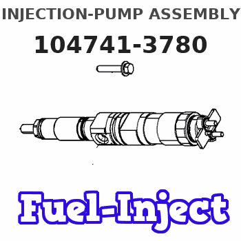
Information injection-pump assembly
BOSCH
9 460 613 496
9460613496
ZEXEL
104741-3780
1047413780
Rating:
Cross reference number
BOSCH
9 460 613 496
9460613496
ZEXEL
104741-3780
1047413780
Zexel num
Bosch num
Firm num
Name
Calibration Data:
Adjustment conditions
Test oil
1404 Test oil ISO4113orSAEJ967d
1404 Test oil ISO4113orSAEJ967d
Test oil temperature
degC
45
45
50
Nozzle
105780-0060
Bosch type code
NP-DN0SD1510
Nozzle holder
105780-2150
Opening pressure
MPa
13
13
13.3
Opening pressure
kgf/cm2
133
133
136
Injection pipe
157805-7320
Injection pipe
Outer diameter - inner diameter - length (mm) mm 2-6-450
Outer diameter - inner diameter - length (mm) mm 2-6-450
Joint assembly
157641-4720
Tube assembly
157641-4020
Transfer pump pressure
kPa
20
20
20
Transfer pump pressure
kgf/cm2
0.2
0.2
0.2
Direction of rotation (viewed from drive side)
Right R
Right R
Injection timing adjustment
Pump speed
r/min
750
750
750
Boost pressure
kPa
0
0
0
Boost pressure
kgf/cm2
0
0
0
Boost pressure
mmHg
0
0
0
Average injection quantity
mm3/st.
57.1
56.6
57.6
Difference in delivery
mm3/st.
4.5
Basic
*
Oil temperature
degC
50
48
52
Remarks
NA
NA
Injection timing adjustment_02
Pump speed
r/min
750
750
750
Boost pressure
kPa
46.7
45.4
48
Boost pressure
kgf/cm2
0.48
0.466
0.494
Boost pressure
mmHg
350
340
360
Average injection quantity
mm3/st.
73.8
73.3
74.3
Difference in delivery
mm3/st.
5.5
Basic
*
Oil temperature
degC
50
48
52
Remarks
CBS
CBS
Injection timing adjustment_03
Pump speed
r/min
1000
1000
1000
Boost pressure
kPa
73.3
72
74.6
Boost pressure
kgf/cm2
0.75
0.736
0.764
Boost pressure
mmHg
550
540
560
Average injection quantity
mm3/st.
84.4
83.9
84.9
Difference in delivery
mm3/st.
6.5
Basic
*
Oil temperature
degC
50
48
52
Remarks
Full
Full
Injection timing adjustment_04
Pump speed
r/min
750
750
750
Boost pressure
kPa
0
0
0
Boost pressure
kgf/cm2
0
0
0
Boost pressure
mmHg
0
0
0
Average injection quantity
mm3/st.
57.1
56.1
58.1
Basic
*
Oil temperature
degC
50
48
52
Remarks
NA
NA
Injection timing adjustment_05
Pump speed
r/min
750
750
750
Boost pressure
kPa
46.7
45.4
48
Boost pressure
kgf/cm2
0.48
0.466
0.494
Boost pressure
mmHg
350
340
360
Average injection quantity
mm3/st.
73.8
72.8
74.8
Basic
*
Oil temperature
degC
50
48
52
Remarks
CBS
CBS
Injection timing adjustment_06
Pump speed
r/min
1000
1000
1000
Boost pressure
kPa
73.3
72
74.6
Boost pressure
kgf/cm2
0.75
0.736
0.764
Boost pressure
mmHg
550
540
560
Average injection quantity
mm3/st.
84.4
83.4
85.4
Difference in delivery
mm3/st.
7
Basic
*
Oil temperature
degC
50
48
52
Remarks
Full
Full
Injection timing adjustment_07
Pump speed
r/min
2000
2000
2000
Boost pressure
kPa
73.3
72
74.6
Boost pressure
kgf/cm2
0.75
0.736
0.764
Boost pressure
mmHg
550
540
560
Average injection quantity
mm3/st.
71.8
67.8
75.8
Oil temperature
degC
50
48
52
Injection quantity adjustment
Pump speed
r/min
2475
2475
2475
Boost pressure
kPa
73.3
72
74.6
Boost pressure
kgf/cm2
0.75
0.736
0.764
Boost pressure
mmHg
550
540
560
Average injection quantity
mm3/st.
26.4
23.4
29.4
Difference in delivery
mm3/st.
8
Basic
*
Oil temperature
degC
55
52
58
Injection quantity adjustment_02
Pump speed
r/min
3000
3000
3000
Boost pressure
kPa
73.3
72
74.6
Boost pressure
kgf/cm2
0.75
0.736
0.764
Boost pressure
mmHg
550
540
560
Average injection quantity
mm3/st.
8
Oil temperature
degC
55
52
58
Injection quantity adjustment_03
Pump speed
r/min
2475
2475
2475
Boost pressure
kPa
73.3
72
74.6
Boost pressure
kgf/cm2
0.75
0.736
0.764
Boost pressure
mmHg
550
540
560
Average injection quantity
mm3/st.
26.4
21.4
31.4
Difference in delivery
mm3/st.
8.5
Basic
*
Oil temperature
degC
55
52
58
Governor adjustment
Pump speed
r/min
375
375
375
Boost pressure
kPa
0
0
0
Boost pressure
kgf/cm2
0
0
0
Boost pressure
mmHg
0
0
0
Average injection quantity
mm3/st.
18.9
16.9
20.9
Difference in delivery
mm3/st.
2
Basic
*
Oil temperature
degC
48
46
50
Governor adjustment_02
Pump speed
r/min
375
375
375
Boost pressure
kPa
0
0
0
Boost pressure
kgf/cm2
0
0
0
Boost pressure
mmHg
0
0
0
Average injection quantity
mm3/st.
18.9
16.4
21.4
Difference in delivery
mm3/st.
2.5
Basic
*
Oil temperature
degC
48
46
50
Governor adjustment_03
Pump speed
r/min
750
750
750
Boost pressure
kPa
0
0
0
Boost pressure
kgf/cm2
0
0
0
Boost pressure
mmHg
0
0
0
Average injection quantity
mm3/st.
5
Oil temperature
degC
50
48
52
Timer adjustment
Pump speed
r/min
150
150
150
Boost pressure
kPa
0
0
0
Boost pressure
kgf/cm2
0
0
0
Boost pressure
mmHg
0
0
0
Average injection quantity
mm3/st.
78.1
58.1
98.1
Oil temperature
degC
48
46
50
Remarks
Full
Full
Timer adjustment_02
Pump speed
r/min
150
150
150
Boost pressure
kPa
0
0
0
Boost pressure
kgf/cm2
0
0
0
Boost pressure
mmHg
0
0
0
Average injection quantity
mm3/st.
78.1
58.1
98.1
Oil temperature
degC
48
46
50
Remarks
Full
Full
Speed control lever angle
Pump speed
r/min
375
375
375
Boost pressure
kPa
0
0
0
Boost pressure
kgf/cm2
0
0
0
Boost pressure
mmHg
0
0
0
Average injection quantity
mm3/st.
0
0
0
Oil temperature
degC
48
46
50
Remarks
Magnet OFF at idling position
Magnet OFF at idling position
0000000901
Pump speed
r/min
1250
1250
1250
Boost pressure
kPa
73.3
72
74.6
Boost pressure
kgf/cm2
0.75
0.736
0.764
Boost pressure
mmHg
550
540
560
Overflow quantity
cm3/min
740
610
870
Oil temperature
degC
50
48
52
Stop lever angle
Pump speed
r/min
1000
1000
1000
Boost pressure
kPa
550
540
560
Boost pressure
kgf/cm2
0.75
0.736
0.764
Boost pressure
mmHg
550
540
560
Pressure
kPa
500
480
520
Pressure
kgf/cm2
5.1
4.9
5.3
Basic
*
Oil temperature
degC
50
48
52
0000001101
Pump speed
r/min
1000
1000
1000
Boost pressure
kPa
73.3
72
74.6
Boost pressure
kgf/cm2
0.75
0.736
0.764
Boost pressure
mmHg
550
540
560
Timer stroke
mm
3.7
3.5
3.9
Basic
*
Oil temperature
degC
50
48
52
_02
Pump speed
r/min
750
750
750
Boost pressure
kPa
73.3
72
74.6
Boost pressure
kgf/cm2
0.75
0.736
0.764
Boost pressure
mmHg
550
540
560
Timer stroke
mm
1.7
1.1
2.3
Oil temperature
degC
50
48
52
_03
Pump speed
r/min
1000
1000
1000
Boost pressure
kPa
73.3
72
74.6
Boost pressure
kgf/cm2
0.75
0.736
0.764
Boost pressure
mmHg
550
540
560
Timer stroke
mm
3.7
3.3
4.1
Basic
*
Oil temperature
degC
50
48
52
_04
Pump speed
r/min
1500
1500
1500
Boost pressure
kPa
73.3
72
74.6
Boost pressure
kgf/cm2
0.75
0.736
0.764
Boost pressure
mmHg
550
540
560
Timer stroke
mm
6.9
6.3
7.5
Oil temperature
degC
50
48
52
_05
Pump speed
r/min
2000
2000
2000
Boost pressure
kPa
73.3
72
74.6
Boost pressure
kgf/cm2
0.75
0.736
0.764
Boost pressure
mmHg
550
540
560
Timer stroke
mm
8.6
8.1
9
Oil temperature
degC
50
48
52
0000001201
Max. applied voltage
V
8
8
8
Test voltage
V
13
12
14
Timing setting
K dimension
mm
3.3
3.2
3.4
KF dimension
mm
5.8
5.7
5.9
MS dimension
mm
0.9
0.8
1
BCS stroke
mm
5.5
5.3
5.7
Control lever angle alpha
deg.
59
55
63
Control lever angle beta
deg.
41
36
46
Information:
* Select an appropriate cleaning method according to the condition of the cooling system as shown below.
* FUSO DIESEL LONGLIFE COOLANT is flammable. Keep them away from heat and flames.
* If you accidentally splash FUSO DIESEL LONGLIFE COOLANT, FUSO ANTIFREEZE, OR RADIATOR ANTIRUST (RADIPET 9) in your eyes, wash it out immediately with water and seek medical attention.
Air Bleeding of Cooling System
* With the pressure cap removed and the coolant temperature at 90°C, let the engine idle in order to bleed air completely out of the cooling system.* After air bleeding is completed, refill the reservoir tank with coolant as needed.Air/Gas Leakage Test
* Presence of air or exhaust gas in coolant accelerates corrosion of the cooling system components. To prevent this, carry out air/gas leakage tests in accordance with the following procedure.* Remove the pressure cap.
* If the engine is hot, boiling coolant may spurt out from the filler port when the pressure cap is loosened. To avoid being scold, make sure to remove the pressure cap only when the coolant is cold.
* Run the engine until the coolant temperature rises to approximately 90°C. * If air bubbles appear continuously through the filler port, there is air or exhaust gas penetrating into the cooling system.* Presence of air in coolant can be an indication of loose cylinder head bolts, loose water pump mounting bolts, loose hose connections, and/or a damaged hose.* Presence of exhaust gas in coolant can be an indication of a damaged cylinder head gasket and/or cracks in the cylinder head.Inspection of Coolant Leak
* With the engine idling, check the coolant passage (radiator hose, water hose, etc.) for coolant leak.* If any leak is found, check the installation condition of each part and retighten the loose part to the specified torque.If any crack or damage is found on a pipe or hose, replace it to a new one.Coolant Fan, Belt And Water Pump
Removal Sequence1 Cooling fan2 Fan spacer3 Belt4 Water pump pulley5 Water pump6 O-ringX: Non-reusable parts* The water pump cannot be disassembled. It must be replaced if defective. Installation SequenceFollow the removal sequence in reverse.
* The water pump pulley is driven by two belts. Always replace the two belts simultaneously to ensure that both belts have the same tension.* Make sure that there is no oil or grease on the belts. Belts soiled with oil or grease may easily slip, resulting in deteriorated performance of the cooling system.* Keep the O-ring free from engine oil. Engine oil will make the O-ring swell, which may cause leakage.
* After installation, check and adjust the belt tension. (See "GENERAL INSPECTION AND ADJUSTMENT".)Lubricant and/or sealant Water Hose And Pipe
Disassembly Sequence1 Heater return pipe2 O-ring3 Water temperature sensor4 Water outlet pipe5 Gasket*a: Thermostat caseX: Non-reusable parts Assembly SequenceFollow the disassembly sequence in reverse.
* Keep the O-ring free of engine oil. Engine oil will make the O-ring swell, which may cause leakage.
Tightening Torque (Unit: N m {kgf m}) Lubricant and/or sealant Thermostat
Disassembly Sequence1 Thermostat cover2 Thermostat3 Bypass Pipe4 O-ring5 Thermostat