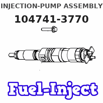
Information injection-pump assembly
BOSCH
9 460 613 495
9460613495
ZEXEL
104741-3770
1047413770
Rating:
Cross reference number
BOSCH
9 460 613 495
9460613495
ZEXEL
104741-3770
1047413770
Zexel num
Bosch num
Firm num
Name
Calibration Data:
Adjustment conditions
Test oil
1404 Test oil ISO4113orSAEJ967d
1404 Test oil ISO4113orSAEJ967d
Test oil temperature
degC
45
45
50
Nozzle
105780-0060
Bosch type code
NP-DN0SD1510
Nozzle holder
105780-2150
Opening pressure
MPa
13
13
13.3
Opening pressure
kgf/cm2
133
133
136
Injection pipe
157805-7320
Injection pipe
Inside diameter - outside diameter - length (mm) mm 2-6-450
Inside diameter - outside diameter - length (mm) mm 2-6-450
Joint assembly
157641-4720
Tube assembly
157641-4020
Transfer pump pressure
kPa
20
20
20
Transfer pump pressure
kgf/cm2
0.2
0.2
0.2
Direction of rotation (viewed from drive side)
Right R
Right R
Injection timing adjustment
Pump speed
r/min
750
750
750
Boost pressure
kPa
0
0
0
Boost pressure
kgf/cm2
0
0
0
Boost pressure
mmHg
0
0
0
Average injection quantity
mm3/st.
57.1
56.6
57.6
Difference in delivery
mm3/st.
4.5
Basic
*
Oil temperature
degC
50
48
52
Remarks
NA
NA
Injection timing adjustment_02
Pump speed
r/min
750
750
750
Boost pressure
kPa
46.7
45.4
48
Boost pressure
kgf/cm2
0.48
0.466
0.494
Boost pressure
mmHg
350
340
360
Average injection quantity
mm3/st.
73.8
73.3
74.3
Difference in delivery
mm3/st.
5.5
Basic
*
Oil temperature
degC
50
48
52
Remarks
CBS
CBS
Injection timing adjustment_03
Pump speed
r/min
1000
1000
1000
Boost pressure
kPa
73.3
72
74.6
Boost pressure
kgf/cm2
0.75
0.736
0.764
Boost pressure
mmHg
550
540
560
Average injection quantity
mm3/st.
84.4
83.9
84.9
Difference in delivery
mm3/st.
6.5
Basic
*
Oil temperature
degC
50
48
52
Remarks
Full
Full
Injection timing adjustment_04
Pump speed
r/min
750
750
750
Boost pressure
kPa
0
0
0
Boost pressure
kgf/cm2
0
0
0
Boost pressure
mmHg
0
0
0
Average injection quantity
mm3/st.
57.1
56.1
58.1
Basic
*
Oil temperature
degC
50
48
52
Remarks
NA
NA
Injection timing adjustment_05
Pump speed
r/min
750
750
750
Boost pressure
kPa
46.7
45.4
48
Boost pressure
kgf/cm2
0.48
0.466
0.494
Boost pressure
mmHg
350
340
360
Average injection quantity
mm3/st.
73.8
72.8
74.8
Basic
*
Oil temperature
degC
50
48
52
Remarks
CBS
CBS
Injection timing adjustment_06
Pump speed
r/min
1000
1000
1000
Boost pressure
kPa
73.3
72
74.6
Boost pressure
kgf/cm2
0.75
0.736
0.764
Boost pressure
mmHg
550
540
560
Average injection quantity
mm3/st.
84.4
83.4
85.4
Difference in delivery
mm3/st.
7
Basic
*
Oil temperature
degC
50
48
52
Remarks
Full
Full
Injection timing adjustment_07
Pump speed
r/min
2000
2000
2000
Boost pressure
kPa
73.3
72
74.6
Boost pressure
kgf/cm2
0.75
0.736
0.764
Boost pressure
mmHg
550
540
560
Average injection quantity
mm3/st.
71.8
67.8
75.8
Oil temperature
degC
50
48
52
Injection quantity adjustment
Pump speed
r/min
2475
2475
2475
Boost pressure
kPa
73.3
72
74.6
Boost pressure
kgf/cm2
0.75
0.736
0.764
Boost pressure
mmHg
550
540
560
Average injection quantity
mm3/st.
26.4
23.4
29.4
Difference in delivery
mm3/st.
8
Basic
*
Oil temperature
degC
55
52
58
Injection quantity adjustment_02
Pump speed
r/min
3000
3000
3000
Boost pressure
kPa
73.3
72
74.6
Boost pressure
kgf/cm2
0.75
0.736
0.764
Boost pressure
mmHg
550
540
560
Average injection quantity
mm3/st.
8
Oil temperature
degC
55
52
58
Injection quantity adjustment_03
Pump speed
r/min
2475
2475
2475
Boost pressure
kPa
73.3
72
74.6
Boost pressure
kgf/cm2
0.75
0.736
0.764
Boost pressure
mmHg
550
540
560
Average injection quantity
mm3/st.
26.4
21.4
31.4
Difference in delivery
mm3/st.
8.5
Basic
*
Oil temperature
degC
55
52
58
Governor adjustment
Pump speed
r/min
375
375
375
Boost pressure
kPa
0
0
0
Boost pressure
kgf/cm2
0
0
0
Boost pressure
mmHg
0
0
0
Average injection quantity
mm3/st.
18.9
16.9
20.9
Difference in delivery
mm3/st.
2
Basic
*
Oil temperature
degC
48
46
50
Governor adjustment_02
Pump speed
r/min
375
375
375
Boost pressure
kPa
0
0
0
Boost pressure
kgf/cm2
0
0
0
Boost pressure
mmHg
0
0
0
Average injection quantity
mm3/st.
18.9
16.4
21.4
Difference in delivery
mm3/st.
2.5
Basic
*
Oil temperature
degC
48
46
50
Governor adjustment_03
Pump speed
r/min
750
750
750
Boost pressure
kPa
0
0
0
Boost pressure
kgf/cm2
0
0
0
Boost pressure
mmHg
0
0
0
Average injection quantity
mm3/st.
5
Oil temperature
degC
50
48
52
Timer adjustment
Pump speed
r/min
150
150
150
Boost pressure
kPa
0
0
0
Boost pressure
kgf/cm2
0
0
0
Boost pressure
mmHg
0
0
0
Average injection quantity
mm3/st.
78.1
58.1
98.1
Oil temperature
degC
48
46
50
Remarks
Full
Full
Timer adjustment_02
Pump speed
r/min
150
150
150
Boost pressure
kPa
0
0
0
Boost pressure
kgf/cm2
0
0
0
Boost pressure
mmHg
0
0
0
Average injection quantity
mm3/st.
78.1
58.1
98.1
Oil temperature
degC
48
46
50
Remarks
Full
Full
Speed control lever angle
Pump speed
r/min
375
375
375
Boost pressure
kPa
0
0
0
Boost pressure
kgf/cm2
0
0
0
Boost pressure
mmHg
0
0
0
Average injection quantity
mm3/st.
0
0
0
Oil temperature
degC
48
46
50
Remarks
Magnet OFF at idling position
Magnet OFF at idling position
0000000901
Pump speed
r/min
1250
1250
1250
Boost pressure
kPa
73.3
72
74.6
Boost pressure
kgf/cm2
0.75
0.736
0.764
Boost pressure
mmHg
550
540
560
Overflow quantity
cm3/min
740
610
870
Oil temperature
degC
50
48
52
Stop lever angle
Pump speed
r/min
1000
1000
1000
Boost pressure
kPa
73.3
72
74.6
Boost pressure
kgf/cm2
0.75
0.736
0.764
Boost pressure
mmHg
550
540
560
Pressure
kPa
500
480
520
Pressure
kgf/cm2
5.1
4.9
5.3
Basic
*
Oil temperature
degC
50
48
52
0000001101
Pump speed
r/min
1000
1000
1000
Boost pressure
kPa
73.3
72
74.6
Boost pressure
kgf/cm2
0.75
0.736
0.764
Boost pressure
mmHg
550
540
560
Timer stroke
mm
3.7
3.5
3.9
Basic
*
Oil temperature
degC
50
48
52
_02
Pump speed
r/min
750
750
750
Boost pressure
kPa
73.3
72
74.6
Boost pressure
kgf/cm2
0.75
0.736
0.764
Boost pressure
mmHg
550
540
560
Timer stroke
mm
1.7
1.1
2.3
Oil temperature
degC
50
48
52
_03
Pump speed
r/min
1000
1000
1000
Boost pressure
kPa
73.3
72
74.6
Boost pressure
kgf/cm2
0.75
0.736
0.764
Boost pressure
mmHg
550
540
560
Timer stroke
mm
3.7
3.3
4.1
Basic
*
Oil temperature
degC
50
48
52
_04
Pump speed
r/min
1500
1500
1500
Boost pressure
kPa
73.3
72
74.6
Boost pressure
kgf/cm2
0.75
0.736
0.764
Boost pressure
mmHg
550
540
560
Timer stroke
mm
6.9
6.3
7.5
Oil temperature
degC
50
48
52
_05
Pump speed
r/min
2000
2000
2000
Boost pressure
kPa
73.3
72
74.6
Boost pressure
kgf/cm2
0.75
0.736
0.764
Boost pressure
mmHg
550
540
560
Timer stroke
mm
8.6
8.1
9
Oil temperature
degC
50
48
52
0000001201
Max. applied voltage
V
8
8
8
Test voltage
V
13
12
14
Timing setting
K dimension
mm
3.3
3.2
3.4
KF dimension
mm
5.8
5.7
5.9
MS dimension
mm
0.9
0.8
1
BCS stroke
mm
5.5
5.3
5.7
Control lever angle alpha
deg.
59
55
63
Control lever angle beta
deg.
41
36
46
Information:
Installation procedure
Installation: Oil pan* Clean the sealant application surfaces of each part. * Apply a bead of sealant to each of the mating surfaces of the timing gear case, lower crankcase and front plate (at the two locations indicated the illustration). Installation: Oil pan* Clean the mating surfaces of each part. * Apply a bead of sealant to the mating surface of the oil pan evenly and without any breaks.* Mount the oil pan within three minutes of applying the sealant. Make sure that the sealant stays in place.
* Do not start the engine less than an hour after installation. If the oil pan mounting bolts were loosened or removed, be sure to reapply sealant.
Oil Pump
* Disassembly sequence1 Oil pump cover2 Driven gear3 Plug4 Relief valve spring5 Steel ball6 Gear and case7 O-ring*a Drive gear*b Oil pump gearP Locating pinX Non-reusable parts* Assembly sequenceFollow the disassembly procedure in reverse.Service standards (Unit: mm) Tightening torque (Unit: N m {kgf m}) Lubricant and/or sealant Inspection procedure
Inspection: Oil pump cover, driven gear, and gear and case* Measure the clearance between each gear's shaft and the oil pump cover, as well as between each gear's shaft and the gear and case. * If the measurements are not within the standard value range, replace the defective part(s). Inspection: Driven gear, drive gear and gear and case* Carry out the following inspection. Replace the oil pump if any defects are found. (1) Sinkage of each gear from gear and case end surface(2) Gear and case-to-tooth tip clearance for each gear Oil Cooler <Engine-Mounted Type, Engine Separately Mounted Type>, and Oil Filter <Engine-Mounted Type>
* Wipe up any spilled engine oil, as it can cause fires.* To avoid any risks of burns, take care not to touch the engine oil when the engine is hot.
* Make sure not to put any engine oil on the belt when working on the oil cooler and oil filter. Belt soiled with oil or grease may easily slip, resulting in deteriorated performance of the cooling system.* Do not reuse the oil filter elements by washing.
* Removal sequence1 Oil filter2 Plug3 Regulator valve spring4 Regulator valve5 Plug6 Bypass valve spring7 Bypass valve8 Oil cooler element9 Gasket10 Water drain plug11 Oil cooler body12 O-ring13 Gasket14 Water separate lipX Non-reusable parts* Installation sequenceFollow the removal sequence in reverse.Service standards (Unit: mm) Tightening torque (Unit: N m {kgf m}) Lubricant and/or sealant Special tools Removal procedure
Removal: Oil filter <Engine-mounted type> Inspection procedure
Inspection: Oil cooler element* Plug the outlet of the oil cooler element and connect a hose to the engine oil inlet port. Then, immerse the oil cooler element in a tank of water. * Apply an air pressure of 1.5 MPa {15 kgf/cm2} for 15 seconds through the hose, and check for any air leaks.* Replace the element if it leaks air.Installation procedure
Installation: Oil cooler <Engine-mounted type>* Clean the oil filter mounting surface of the oil cooler. * Apply a thin coat of engine oil on the oil filter gasket.* Screw in the