Information injection-pump assembly
ZEXEL
104741-3140
1047413140

Rating:
Cross reference number
ZEXEL
104741-3140
1047413140
Zexel num
Bosch num
Firm num
Name
104741-3140
INJECTION-PUMP ASSEMBLY
Calibration Data:
Adjustment conditions
Test oil
1404 Test oil ISO4113orSAEJ967d
1404 Test oil ISO4113orSAEJ967d
Test oil temperature
degC
45
45
50
Nozzle
105780-0060
Bosch type code
NP-DN0SD1510
Nozzle holder
105780-2150
Opening pressure
MPa
13
13
13.3
Opening pressure
kgf/cm2
133
133
136
Injection pipe
157805-7320
Injection pipe
Inside diameter - outside diameter - length (mm) mm 2-6-450
Inside diameter - outside diameter - length (mm) mm 2-6-450
Joint assembly
157641-4720
Tube assembly
157641-4020
Transfer pump pressure
kPa
20
20
20
Transfer pump pressure
kgf/cm2
0.2
0.2
0.2
Direction of rotation (viewed from drive side)
Right R
Right R
Injection timing adjustment
Pump speed
r/min
600
600
600
Boost pressure
kPa
31.3
30
32.6
Boost pressure
kgf/cm2
0.32
0.306
0.334
Boost pressure
mmHg
235
225
245
Average injection quantity
mm3/st.
67.3
66.8
67.8
Difference in delivery
mm3/st.
5.5
Basic
*
Oil temperature
degC
50
48
52
Remarks
CBS
CBS
Injection timing adjustment_02
Pump speed
r/min
750
750
750
Boost pressure
kPa
0
0
0
Boost pressure
kgf/cm2
0
0
0
Boost pressure
mmHg
0
0
0
Average injection quantity
mm3/st.
57.2
56.7
57.7
Difference in delivery
mm3/st.
4.5
Basic
*
Oil temperature
degC
50
48
52
Remarks
NA
NA
Injection timing adjustment_03
Pump speed
r/min
1000
1000
1000
Boost pressure
kPa
73.3
72
74.6
Boost pressure
kgf/cm2
0.75
0.736
0.764
Boost pressure
mmHg
550
540
560
Average injection quantity
mm3/st.
81.3
80.8
81.8
Difference in delivery
mm3/st.
6.5
Basic
*
Oil temperature
degC
50
48
52
Remarks
Full
Full
Injection timing adjustment_04
Pump speed
r/min
600
600
600
Boost pressure
kPa
31.3
30
32.6
Boost pressure
kgf/cm2
0.32
0.306
0.334
Boost pressure
mmHg
235
225
245
Average injection quantity
mm3/st.
67.3
66.3
68.3
Basic
*
Oil temperature
degC
50
48
52
Remarks
CBS
CBS
Injection timing adjustment_05
Pump speed
r/min
750
750
750
Boost pressure
kPa
0
0
0
Boost pressure
kgf/cm2
0
0
0
Boost pressure
mmHg
0
0
0
Average injection quantity
mm3/st.
57.2
56.2
58.2
Basic
*
Oil temperature
degC
50
48
52
Remarks
NA
NA
Injection timing adjustment_06
Pump speed
r/min
1000
1000
1000
Boost pressure
kPa
73.3
72
74.6
Boost pressure
kgf/cm2
0.75
0.736
0.764
Boost pressure
mmHg
550
540
560
Average injection quantity
mm3/st.
81.3
80.3
82.3
Difference in delivery
mm3/st.
7
Basic
*
Oil temperature
degC
50
48
52
Remarks
Full
Full
Injection timing adjustment_07
Pump speed
r/min
2000
2000
2000
Boost pressure
kPa
73.3
72
74.6
Boost pressure
kgf/cm2
0.75
0.736
0.764
Boost pressure
mmHg
550
540
560
Average injection quantity
mm3/st.
74.4
70.4
78.4
Oil temperature
degC
50
48
52
Injection quantity adjustment
Pump speed
r/min
2300
2300
2300
Boost pressure
kPa
73.3
72
74.6
Boost pressure
kgf/cm2
0.75
0.736
0.764
Boost pressure
mmHg
550
540
560
Average injection quantity
mm3/st.
56.8
53.8
59.8
Difference in delivery
mm3/st.
17
Basic
*
Oil temperature
degC
52
50
54
Injection quantity adjustment_02
Pump speed
r/min
3000
3000
3000
Boost pressure
kPa
73.3
72
74.6
Boost pressure
kgf/cm2
0.75
0.736
0.764
Boost pressure
mmHg
550
540
560
Average injection quantity
mm3/st.
7
Oil temperature
degC
55
52
58
Injection quantity adjustment_03
Pump speed
r/min
2300
2300
2300
Boost pressure
kPa
73.3
72
74.6
Boost pressure
kgf/cm2
0.75
0.736
0.764
Boost pressure
mmHg
550
540
560
Average injection quantity
mm3/st.
56.8
51.8
61.8
Difference in delivery
mm3/st.
17.5
Basic
*
Oil temperature
degC
52
50
54
Governor adjustment
Pump speed
r/min
365
365
365
Boost pressure
kPa
0
0
0
Boost pressure
kgf/cm2
0
0
0
Boost pressure
mmHg
0
0
0
Average injection quantity
mm3/st.
12.4
10.4
14.4
Difference in delivery
mm3/st.
2
Basic
*
Oil temperature
degC
48
46
50
Governor adjustment_02
Pump speed
r/min
365
365
365
Boost pressure
kPa
0
0
0
Boost pressure
kgf/cm2
0
0
0
Boost pressure
mmHg
0
0
0
Average injection quantity
mm3/st.
12.4
9.9
14.9
Difference in delivery
mm3/st.
2.5
Basic
*
Oil temperature
degC
48
46
50
Boost compensator adjustment
Pump speed
r/min
750
750
750
Boost pressure
kPa
0
0
0
Boost pressure
kgf/cm2
0
0
0
Boost pressure
mmHg
0
0
0
Average injection quantity
mm3/st.
30.7
30.7
30.7
Oil temperature
degC
50
48
52
Lever angle (shim thickness)
mm
21.2
21.2
21.2
Timer adjustment
Pump speed
r/min
150
150
150
Boost pressure
kPa
0
0
0
Boost pressure
kgf/cm2
0
0
0
Boost pressure
mmHg
0
0
0
Average injection quantity
mm3/st.
52
42
62
Basic
*
Oil temperature
degC
48
46
50
Remarks
IDLE
IDLE
Timer adjustment_02
Pump speed
r/min
150
150
150
Boost pressure
kPa
0
0
0
Boost pressure
kgf/cm2
0
0
0
Boost pressure
mmHg
0
0
0
Average injection quantity
mm3/st.
52
42
62
Oil temperature
degC
48
46
50
Remarks
IDLE
IDLE
Speed control lever angle
Pump speed
r/min
365
365
365
Boost pressure
kPa
0
0
0
Boost pressure
kgf/cm2
0
0
0
Boost pressure
mmHg
0
0
0
Average injection quantity
mm3/st.
0
0
0
Oil temperature
degC
48
46
50
Remarks
Magnet OFF at idling position
Magnet OFF at idling position
0000000901
Pump speed
r/min
1250
1250
1250
Boost pressure
kPa
73.3
72
74.6
Boost pressure
kgf/cm2
0.75
0.736
0.764
Boost pressure
mmHg
550
540
560
Overflow quantity
cm3/min
740
610
870
Oil temperature
degC
50
48
52
Stop lever angle
Pump speed
r/min
1250
1250
1250
Boost pressure
kPa
73.3
72
74.6
Boost pressure
kgf/cm2
0.75
0.736
0.764
Boost pressure
mmHg
550
540
560
Pressure
kPa
559
539
579
Pressure
kgf/cm2
5.7
5.5
5.9
Basic
*
Oil temperature
degC
50
48
52
Stop lever angle_02
Pump speed
r/min
700
700
700
Boost pressure
kPa
73.3
72
74.6
Boost pressure
kgf/cm2
0.75
0.736
0.764
Boost pressure
mmHg
550
540
560
Pressure
kPa
422
373
471
Pressure
kgf/cm2
4.3
3.8
4.8
Oil temperature
degC
50
48
52
Stop lever angle_03
Pump speed
r/min
1250
1250
1250
Boost pressure
kPa
73.3
72
74.6
Boost pressure
kgf/cm2
0.75
0.736
0.764
Boost pressure
mmHg
550
540
560
Pressure
kPa
559
530
588
Pressure
kgf/cm2
5.7
5.4
6
Basic
*
Oil temperature
degC
50
48
52
Stop lever angle_04
Pump speed
r/min
1500
1500
1500
Boost pressure
kPa
73.3
72
74.6
Boost pressure
kgf/cm2
0.75
0.736
0.764
Boost pressure
mmHg
550
540
560
Pressure
kPa
608
559
657
Pressure
kgf/cm2
6.2
5.7
6.7
Oil temperature
degC
50
48
52
Stop lever angle_05
Pump speed
r/min
2000
2000
2000
Boost pressure
kPa
73.3
72
74.6
Boost pressure
kgf/cm2
0.75
0.736
0.764
Boost pressure
mmHg
550
540
560
Pressure
kPa
716
667
765
Pressure
kgf/cm2
7.3
6.8
7.8
Oil temperature
degC
50
48
52
0000001101
Pump speed
r/min
1250
1250
1250
Boost pressure
kPa
73.3
72
74.6
Boost pressure
kgf/cm2
0.75
0.736
0.764
Boost pressure
mmHg
550
540
560
Timer stroke
mm
6.7
6.5
6.9
Basic
*
Oil temperature
degC
50
48
52
_02
Pump speed
r/min
700
700
700
Boost pressure
kPa
73.3
72
74.6
Boost pressure
kgf/cm2
0.75
0.736
0.764
Boost pressure
mmHg
550
540
560
Timer stroke
mm
3.3
2.7
3.9
Oil temperature
degC
50
48
52
_03
Pump speed
r/min
1250
1250
1250
Boost pressure
kPa
73.3
72
74.6
Boost pressure
kgf/cm2
0.75
0.736
0.764
Boost pressure
mmHg
550
540
560
Timer stroke
mm
6.7
6.3
7.1
Basic
*
Oil temperature
degC
50
48
52
_04
Pump speed
r/min
2000
2000
2000
Boost pressure
kPa
73.3
72
74.6
Boost pressure
kgf/cm2
0.75
0.736
0.764
Boost pressure
mmHg
550
540
560
Timer stroke
mm
9.8
9.3
10.2
Oil temperature
degC
50
48
52
0000001201
Max. applied voltage
V
8
8
8
Test voltage
V
13
12
14
Timing setting
K dimension
mm
3.3
3.2
3.4
KF dimension
mm
6.01
5.91
6.11
MS dimension
mm
0.7
0.6
0.8
BCS stroke
mm
5
4.8
5.2
Control lever angle alpha
deg.
59
55
63
Control lever angle beta
deg.
42
37
47
Test data Ex:
0000001601 BOOST COMPENSATOR ADJUSTMENT

BCS adjustment procedure
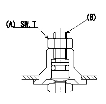
1. At full boost pressure, set so that the full injection quantity is within the specifications (adjusting point).
2. Perform boost compensator intermediate operation point adjustment (pump speed N1, boost pressure P1).
3. When injection quantity at boost pressure P2 and pump speed N2 is not as specified, loosen nut (A) and adjust position of screw (B) so that injection quantity is as specified. The screw position should be within +-1 turn of initial position.
4. The nut tightening torque is T.
----------
N1=600r/min N2=750r/min P1=31.3kPa(235mmHg) P2=0kPa(0mmHg) T=6~9N-m(0.6~0.9kgf-m)
----------
SW=10mm T=6~9N-m(0.6~0.9kgf-m)
----------
N1=600r/min N2=750r/min P1=31.3kPa(235mmHg) P2=0kPa(0mmHg) T=6~9N-m(0.6~0.9kgf-m)
----------
SW=10mm T=6~9N-m(0.6~0.9kgf-m)
0000001801 POTENTIOMETER ADJUSTMENT

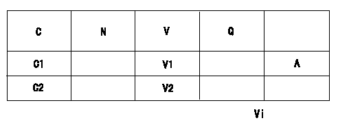
Adjustment of the potentiometer
Vi:Applied voltage
C:Position of the control lever
N:Pump speed
V:Output voltage
Q:Injection quantity
A:Adjusting point
C1:Idling
C2:Full speed
----------
----------
V1=1.6+-0.03V V2=(8.63+-1.5V) Vi=10V
----------
----------
V1=1.6+-0.03V V2=(8.63+-1.5V) Vi=10V
0000001901 ACCELERATOR LINK STROKE

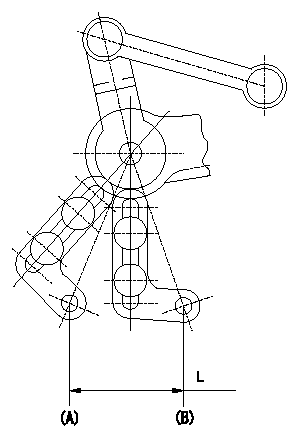
Adjustment of the accelerator link stroke
As shown in the figure, adjust so that the accelerator link's stroke between idle (B) and full speed (A) is L1.
(A): Full-speed
(B): Idle
----------
L=32.9+-1mm
----------
L=32.9+-1mm
----------
L=32.9+-1mm
----------
L=32.9+-1mm
Information:
General Operation Guidelines
For Generator Set Installations of Cat DPF Filter Systems
Ensure that the engine operation will adhere to the Cat DPF Filter ARB verification guidelines below:
At least 30 percent of the operating time the exhaust temperature is above 300° C (572° F) and the engine load is above 40 percent.
Fuel sulfur content is less than 15 ppm, ULSD
Engine PM output of less than 0.2 g/bhp-hr
Insulate all exhaust components between the turbocharger and Cat DPF Filter inlet. This inspection includes piping, expansion joints, and bellows.
Install the Cat DLAS monitor/alarm system as the monitoring/alarm system is the key component to ensuring the Cat DPF Filter unit is working as intended. The monitoring/alarm system also ensures that the filter media is not plugging up with particulate matter. This unit records date, time, temperature and backpressure data, allowing the user a comprehensive understanding of engine duty cycle and Cat DPF Filter performance. Follow the installation instructions carefully. Check the integrity of all plumbing and wiring connections. Once installed, download data using the optional software and check that the temperature and backpressure data correspond to engine load output.
Investigate all warnings that the Cat DLAS generates. Solid yellow or red alarms indicate an increase in backpressure and must be investigated. Blinking yellow or red lights indicate a problem with temperature or pressure measurements and require physical checks of the sensors and connections. Data must be collected when an error is generated.
The data stored in the DLAS is easily down loaded using an Ethernet browser and is required to see real-time data and stored data. This data can then be transferred into Microsoft Excel for viewing and graphing. The data includes a history of all errors generated plus 26,000 lines of temperature, backpressure, time, and date values. This data equates to approximately 100 hours of operation when the logging interval is set at 30 seconds.
Create a schedule for downloading Cat DLAS data and graphing the performance. Backpressure may go up and down but over time should be flat, meaning that particulate is not accumulating on the Cat DPF Filter. If particulate is not accumulating, the Cat DPF Filter is said to be regenerating, or self cleaning. This process is the intended operation of regeneration.
DO NOT operate the generator after a red alarm is triggered. Monitor the backpressure during operation using the Cat DLAS interface to an Ethernet browser or a pressure gauge. If the backpressure continues to increase, stop the engine as soon as possible, and allow the exhaust to cool. Remove the Cat DPF Filter for cleaning. If the backpressure decreases, the engine may continue operation until the backpressure has stabilized. Consult your local Cat dealer.
Continuous low load operation should be limited to under 2 hours. After 2 hours but less than 4 hours, and if no alarms have been triggered, regenerate the Cat DPF Filter by operating the engine at 80 percent to 100 percent load for 45 minutes. The Cat DPF can also be removed for cleaning off the machine or engine.
If
Have questions with 104741-3140?
Group cross 104741-3140 ZEXEL
Mitsubishi
Mitsubishi
Mitsubishi
Mitsubishi
104741-3140
INJECTION-PUMP ASSEMBLY