Information injection-pump assembly
ZEXEL
104741-3010
1047413010
MITSUBISHI
ME200200
me200200

Rating:
Compare Prices: .
As an associate, we earn commssions on qualifying purchases through the links below
You can express buy:
Images:
US $120.00

[13-Dec-2016]
US $120.00

[09-Dec-2016]
US $120.00

[09-Dec-2016]
US $120.00

[29-Apr-2017]
Cross reference number
ZEXEL
104741-3010
1047413010
MITSUBISHI
ME200200
me200200
Zexel num
Bosch num
Firm num
Name
Calibration Data:
Adjustment conditions
Test oil
1404 Test oil ISO4113orSAEJ967d
1404 Test oil ISO4113orSAEJ967d
Test oil temperature
degC
45
45
50
Nozzle
105780-0060
Bosch type code
NP-DN0SD1510
Nozzle holder
105780-2150
Opening pressure
MPa
13
13
13.3
Opening pressure
kgf/cm2
133
133
136
Injection pipe
157805-7320
Injection pipe
Inside diameter - outside diameter - length (mm) mm 2-6-450
Inside diameter - outside diameter - length (mm) mm 2-6-450
Joint assembly
157641-4720
Tube assembly
157641-4020
Transfer pump pressure
kPa
20
20
20
Transfer pump pressure
kgf/cm2
0.2
0.2
0.2
Direction of rotation (viewed from drive side)
Right R
Right R
(Solenoid timer adjustment condition)
With S/T O-ring; S/T OFF. OFF
With S/T O-ring; S/T OFF. OFF
Injection timing adjustment
Pump speed
r/min
550
550
550
Boost pressure
kPa
0
0
0
Boost pressure
mmHg
0
0
0
Average injection quantity
mm3/st.
53.5
53
54
Difference in delivery
mm3/st.
4
Basic
*
Oil temperature
degC
50
48
52
Remarks
NA
NA
Injection timing adjustment_02
Pump speed
r/min
600
600
600
Boost pressure
kPa
31.3
30
32.6
Boost pressure
mmHg
235
225
245
Average injection quantity
mm3/st.
68.2
67.7
68.7
Difference in delivery
mm3/st.
5.5
Basic
*
Oil temperature
degC
50
48
52
Remarks
CBS
CBS
Injection timing adjustment_03
Pump speed
r/min
1000
1000
1000
Boost pressure
kPa
73.3
72
74.6
Boost pressure
mmHg
550
540
560
Average injection quantity
mm3/st.
75.6
75.1
76.1
Difference in delivery
mm3/st.
6
Basic
*
Oil temperature
degC
50
48
52
Remarks
Full
Full
Injection timing adjustment_04
Pump speed
r/min
550
550
550
Boost pressure
kPa
0
0
0
Boost pressure
mmHg
0
0
0
Average injection quantity
mm3/st.
53.5
52.5
54.5
Basic
*
Oil temperature
degC
50
48
52
Remarks
NA
NA
Injection timing adjustment_05
Pump speed
r/min
600
600
600
Boost pressure
kPa
31.3
30
32.6
Boost pressure
mmHg
235
225
245
Average injection quantity
mm3/st.
68.2
67.2
69.2
Basic
*
Oil temperature
degC
50
48
52
Remarks
CBS
CBS
Injection timing adjustment_06
Pump speed
r/min
1000
1000
1000
Boost pressure
kPa
73.3
72
74.6
Boost pressure
mmHg
550
540
560
Average injection quantity
mm3/st.
75.6
74.6
76.6
Difference in delivery
mm3/st.
6.5
Basic
*
Oil temperature
degC
50
48
52
Remarks
Full
Full
Injection timing adjustment_07
Pump speed
r/min
2000
2000
2000
Boost pressure
kPa
73.3
72
74.6
Boost pressure
mmHg
550
540
560
Average injection quantity
mm3/st.
71.4
67.4
75.4
Oil temperature
degC
50
48
52
Injection quantity adjustment
Pump speed
r/min
2475
2475
2475
Boost pressure
kPa
73.3
72
74.6
Boost pressure
mmHg
550
540
560
Average injection quantity
mm3/st.
33
30
36
Difference in delivery
mm3/st.
5
Basic
*
Oil temperature
degC
55
52
58
Injection quantity adjustment_02
Pump speed
r/min
2475
2475
2475
Boost pressure
kPa
73.3
72
74.6
Boost pressure
mmHg
550
540
560
Average injection quantity
mm3/st.
33
28
38
Difference in delivery
mm3/st.
5.5
Basic
*
Oil temperature
degC
55
52
58
Injection quantity adjustment_03
Pump speed
r/min
2800
2800
2800
Boost pressure
kPa
73.3
72
74.6
Boost pressure
mmHg
550
540
560
Average injection quantity
mm3/st.
8
Oil temperature
degC
55
52
58
Governor adjustment
Pump speed
r/min
365
365
365
Boost pressure
kPa
0
0
0
Boost pressure
mmHg
0
0
0
Average injection quantity
mm3/st.
10.5
8.5
12.5
Difference in delivery
mm3/st.
2
Basic
*
Oil temperature
degC
48
46
50
Governor adjustment_02
Pump speed
r/min
365
365
365
Boost pressure
kPa
0
0
0
Boost pressure
mmHg
0
0
0
Average injection quantity
mm3/st.
10.5
8
13
Difference in delivery
mm3/st.
2.5
Basic
*
Oil temperature
degC
48
46
50
Timer adjustment
Pump speed
r/min
100
100
100
Boost pressure
kPa
0
0
0
Boost pressure
mmHg
0
0
0
Average injection quantity
mm3/st.
50
40
60
Basic
*
Oil temperature
degC
48
46
50
Remarks
IDLE
IDLE
Timer adjustment_02
Pump speed
r/min
100
100
100
Boost pressure
kPa
0
0
0
Boost pressure
mmHg
0
0
0
Average injection quantity
mm3/st.
50
40
60
Basic
*
Oil temperature
degC
48
46
50
Speed control lever angle
Pump speed
r/min
365
365
365
Boost pressure
kPa
0
0
0
Boost pressure
mmHg
0
0
0
Average injection quantity
mm3/st.
0
0
0
Oil temperature
degC
48
46
50
Remarks
Magnet OFF at idling position
Magnet OFF at idling position
0000000901
Pump speed
r/min
1100
1100
1100
Boost pressure
kPa
73.3
72
74.6
Boost pressure
mmHg
550
540
560
Overflow quantity with S/T ON
cm3/min
850
720
980
Overflow quantity with S/T OFF
cm3/min
930
800
1060
Oil temperature
degC
50
48
52
Stop lever angle
Pump speed
r/min
1250
1250
1250
Boost pressure
kPa
73.3
72
74.6
Boost pressure
mmHg
550
540
560
Pressure with S/T ON
kPa
559
520
598
Pressure with S/T ON
kgf/cm2
5.7
5.3
6.1
Pressure with S/T OFF
kPa
481
461
501
Pressure with S/T OFF
kgf/cm2
4.9
4.7
5.1
Basic
*
Oil temperature
degC
50
48
52
Stop lever angle_02
Pump speed
r/min
700
700
700
Boost pressure
kPa
73.3
72
74.6
Boost pressure
mmHg
550
540
560
Pressure with S/T ON
kPa
422
373
471
Pressure with S/T ON
kgf/cm2
4.3
3.8
4.8
Pressure with S/T OFF
kPa
284
235
333
Pressure with S/T OFF
kgf/cm2
2.9
2.4
3.4
Oil temperature
degC
50
48
52
Stop lever angle_03
Pump speed
r/min
800
800
800
Boost pressure
kPa
73.3
72
74.6
Boost pressure
mmHg
550
540
560
Pressure with S/T OFF
kPa
353
304
402
Pressure with S/T OFF
kgf/cm2
3.6
3.1
4.1
Oil temperature
degC
50
48
52
Stop lever angle_04
Pump speed
r/min
900
900
900
Boost pressure
kPa
73.3
72
74.6
Boost pressure
mmHg
550
540
560
Pressure with S/T OFF
kPa
392
353
431
Pressure with S/T OFF
kgf/cm2
4
3.6
4.4
Oil temperature
degC
50
48
52
Stop lever angle_05
Pump speed
r/min
1000
1000
1000
Boost pressure
kPa
73.3
72
74.6
Boost pressure
mmHg
550
540
560
Pressure with S/T OFF
kPa
422
383
461
Pressure with S/T OFF
kgf/cm2
4.3
3.9
4.7
Oil temperature
degC
50
48
52
Stop lever angle_06
Pump speed
r/min
1100
1100
1100
Boost pressure
kPa
73.3
72
74.6
Boost pressure
mmHg
550
540
560
Pressure with S/T ON
kPa
530
481
579
Pressure with S/T ON
kgf/cm2
5.4
4.9
5.9
Pressure with S/T OFF
kPa
451
412
490
Pressure with S/T OFF
kgf/cm2
4.6
4.2
5
Oil temperature
degC
50
48
52
Stop lever angle_07
Pump speed
r/min
1250
1250
1250
Boost pressure
kPa
73.3
72
74.6
Boost pressure
mmHg
550
540
560
Pressure with S/T ON
kPa
559
510
608
Pressure with S/T ON
kgf/cm2
5.7
5.2
6.2
Pressure with S/T OFF
kPa
481
452
510
Pressure with S/T OFF
kgf/cm2
4.9
4.6
5.2
Basic
*
Oil temperature
degC
50
48
52
Stop lever angle_08
Pump speed
r/min
2000
2000
2000
Boost pressure
kPa
73.3
72
74.6
Boost pressure
mmHg
550
540
560
Pressure with S/T ON
kPa
696
647
745
Pressure with S/T ON
kgf/cm2
7.1
6.6
7.6
Pressure with S/T OFF
kPa
628
589
667
Pressure with S/T OFF
kgf/cm2
6.4
6
6.8
Oil temperature
degC
50
48
52
0000001101
Pump speed
r/min
1250
1250
1250
Boost pressure
kPa
73.3
72
74.6
Boost pressure
mmHg
550
540
560
Timer stroke with S/T ON
mm
6.7
6.2
7.2
Timer stroke with S/T OFF
mm
4.7
4.5
4.9
Basic
*
Oil temperature
degC
50
48
52
_02
Pump speed
r/min
700
700
700
Boost pressure
kPa
73.3
72
74.6
Boost pressure
mmHg
550
540
560
Timer stroke with S/T ON
mm
3.3
2.6
4
Timer stroke with S/T OFF
mm
0.8
Oil temperature
degC
50
48
52
_03
Pump speed
r/min
1250
1250
1250
Boost pressure
kPa
73.3
72
74.6
Boost pressure
mmHg
550
540
560
Timer stroke with S/T ON
mm
6.7
6
7.4
Timer stroke with S/T OFF
mm
4.7
4.3
5.1
Basic
*
Oil temperature
degC
50
48
52
_04
Pump speed
r/min
2300
2300
2300
Boost pressure
kPa
73.3
72
74.6
Boost pressure
mmHg
550
540
560
Timer stroke with S/T OFF
mm
9.8
9.3
10.2
Oil temperature
degC
52
50
54
0000001201
Max. applied voltage
V
8
8
8
Test voltage
V
13
12
14
Timing setting
K dimension
mm
3.3
3.2
3.4
KF dimension
mm
6.01
5.91
6.11
MS dimension
mm
0.7
0.6
0.8
BCS stroke
mm
4.5
4.3
4.7
Control lever angle alpha
deg.
59
55
63
Control lever angle beta
deg.
42
37
47
Test data Ex:
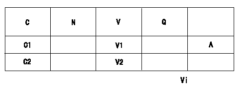
0000001801 POTENTIOMETER ADJUSTMENT

Adjustment of the potentiometer
Vi:Applied voltage
C:Position of the control lever
N:Pump speed
V:Output voltage
Q:Injection quantity
A:Adjusting point
C1:Idling
C2:Full speed
----------
----------
V1=1.6+-0.03(V) V2=(8.6(V)) Vi=10(V)
----------
----------
V1=1.6+-0.03(V) V2=(8.6(V)) Vi=10(V)
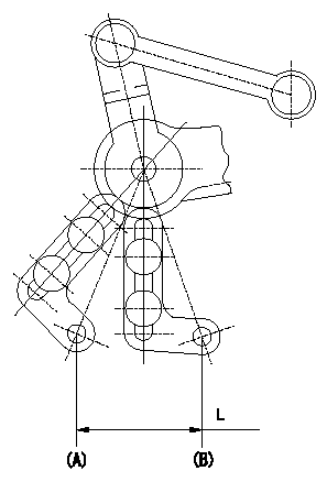
0000001901 ACCELERATOR LINK STROKE

Adjustment of the accelerator link stroke
As shown in the figure, adjust so that the accelerator link's stroke between idle (B) and full speed (A) is L1.
(A): Full-speed
(B): Idle
----------
L=32.9+-1mm
----------
L=32.9+-1mm
----------
L=32.9+-1mm
----------
L=32.9+-1mm
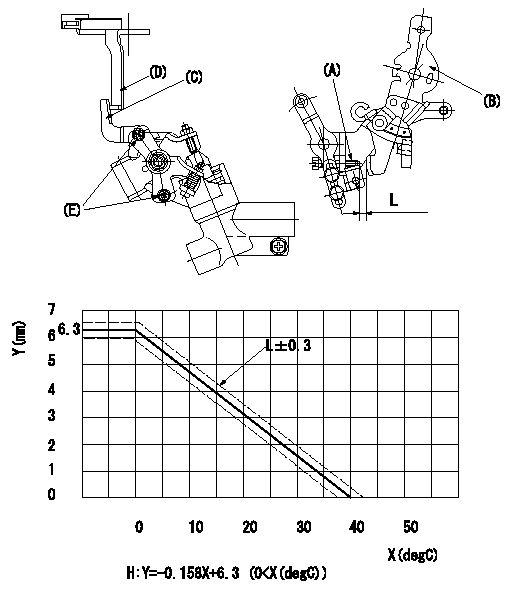
0000002001 W-FICD LEVER ADJUSTMENT

2. W-FICD (E) adjustment
(1)Insert a block gauge L1 determined from the graph between the control lever (B) and the idling set screw (A).
(2)Fix bolt (E) in the position where W-FICD lever (C) contacts the control lever (D). (Tighten to torque T.)
Caution: The temperature of the wax at adjustment must not exceed a.
X = temperature (deg C)
Y = control lever dimension L (control lever position)
(H) = Control lever L mm
----------
L1=L+-0.3(mm) T=3.4~4.9(Nm)(0.35~0.5(kgfm)) a=35(degC)
----------
L1=L+-0.3(mm)
----------
L1=L+-0.3(mm) T=3.4~4.9(Nm)(0.35~0.5(kgfm)) a=35(degC)
----------
L1=L+-0.3(mm)
Information:
Introduction
Do not perform any procedure in this Special Instruction until you have read the information and you understand the information.If the crankshaft, gear case and/or crank gear are replaced, it is necessary to perform the injection timing correction procedure. The following steps show how to calculate/determine the new injection timing by measuring angular deviation between the crankshaft TDC and Crank Position sensor detected TDC.Note: Once complete the engine ecm must be reprogrammed with the new injection timing value. Follow all Steps below.Procedure
Illustration 1 g06220080
(1) TC Mark (Flywheel Housing)
(2) TC Mark (Flywheel)
Remove valve cover, injector, and rocker arm. Bring the piston of cylinder 4 to TDC.
Illustration 2 g06220082
(3) Dial Gauge
(4) Valve
(5) O-ring
Remove the #4 exhaust valve bridge arm and valve spring. Insert a small O-ring (5) so the valve (4) does not fall into the cylinder.
Set the dial gauge (3) on the tip of the valve (4).
Illustration 3 g06220083
(6) Tri-sqaure
(7) Flywheel Housing
(8) Flywheel
Illustration 4 g06220087
(7) Flywheel Housing
(8) Flywheel
(9) Reference Line
Turn the flywheel counterclockwise and measure the position where the tip of the valve is highest.
Stop the flywheel at the position where the tip of the valve is the highest. Put a tri-sqaure (6) on the flywheel housing (7) and the flywheel (8) and draw a reference line (9).Do not drop the valve (4) into the cylinder. When measuring the highest position of the tip of the valve do not rotate the flywheel clockwise. If you go past the highest point of the valve, back up the flywheel slightly and measure the highest point of the valve. The reference line (9) indicates the TDC of the crankshaft.
Illustration 5 g06220092
(10) Tester
(11) Crankshaft Position Sensor
Illustration 6 g06220095
(11) Crankshaft Position Sensor
(12) Ground Terminal
(13) Output Terminal
Connect the engine harness and the main switch. Connect battery.Attach the tester (10) to the output terminal (13) and the ground terminal (12) of the crankshaft position sensor (11). Turn the main switch "ON". Turn the flywheel and make sure that the voltage of the crankshaft position sensor goes from 0→ 5 V or 5 → 0 V.
Illustration 7 g06220100
(14) Pulsar Gear
(15) 14th Tooth
(16) Missing Teeth
Rotate the flywheel and align the crankshaft position sensor to the part of the pulsar gear (14) that is missing teeth (16). The 14th tooth (15) from the missing teeth is the standard. Slowly turn the flywheel counterclockwise and stop the flywheel at the point where the needle of the tester changes momentarily from 0→ 5 V, the 14th tooth. That point is where the crankshaft position sensor detects TDC.
Illustration 8 g06220101
(17) Crankshaft TDC
(18) Detection Point of Crankshaft Position Sensor TDC
Illustration 9 g06220104
(19) Interval
Set the tri-square (6) on the reference line (9) on the flywheel housing side and mark the detection point of the crankshaft position sensor TDC (18) on the flywheel.
Measure the interval (19) between the crankshaft TDC (17) and the detection point of the crankshaft position sensor TDC (18).
Calculation of the fuel injection timing correction 1 mm (0.039 inch): 0.342°.Corrected angle = 0.342° X actual interval.
Overwrite the injection timing correction value on the engine ecm registration website refer to REHS9707, "Registering

